
-For enclosure-related parameters such as IP rating, structural design, and installation conditions, refer to:
Cabinet & Enclosure Parameters
-For practical implementation of the parameters discussed in this article, see Risentric’s switchgear product page:
Switchgear Products
Current-Related Parameters
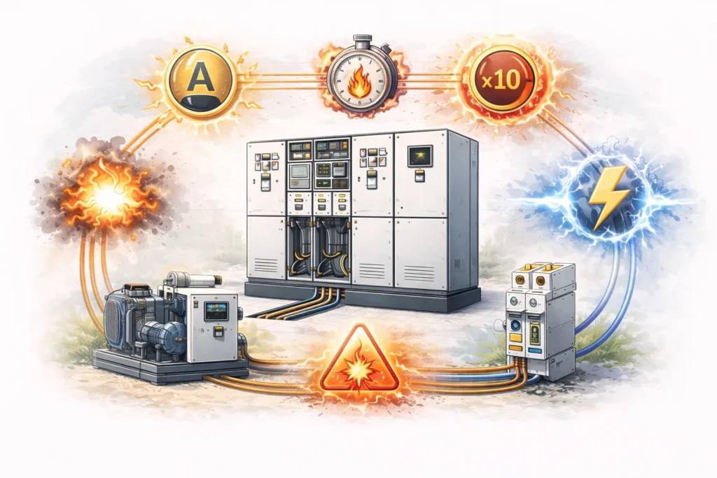
1. Rated Current (In)
Unit: Ampere (A)
Definition: The current that the device can carry continuously under specified conditions, ensuring safe, stable, and efficient operation.
2. Long-Time Delay Setting Current (Ir)
Unit: A
Definition:
The maximum operating current that the circuit breaker can carry continuously.
Operating behavior:
When the current exceeds Ir, the breaker will not trip immediately; it will trip only after a certain delay time. For example: In = 100 A, Ir = 100 A, actual current = 120 A. In this case, it may trip after tens of seconds or several minutes. It mainly protects cables and motors, and prevents long-term overheating damage to equipment.
3. Short-Time Delay Setting Current (Isd)
Unit: kA
Definition:
A high current level that is allowed for a short delay time.
Operating behavior:
Compared with Ir, Isd has a much shorter delay time. It is usually set to several times the rated current (a common adjustable range is about 2–10 × In or higher), with a delay typically from tens to hundreds of milliseconds.
4. Instantaneous Trip Current (Ii)
Unit: kA
Definition:
Instantaneous tripping protection for severe short-circuit faults.
Operating behavior:
It is faster than Isd and is also triggered by excessive current. When the current reaches 8–15 × In (MCB) or 10–20 × In (MCCB/ACB), it trips immediately, usually within a few milliseconds.
5. Rated Ultimate Short-Circuit Breaking Capacity (Icu)
Unit: kA
Definition:
The maximum short-circuit current that the breaker can interrupt once; after interruption, it is not guaranteed to remain usable.
Operating behavior:
Icu is the absolute maximum limit the breaker can interrupt, not a “safe operating comfort zone.” Assume a breaker has Icu = 100 kA, and a short circuit occurs at some point: If the fault current I < Icu, the breaker will trip according to Ir, Isd, and Ii protection functions. The contacts open, the arc is stretched and guided into the arc chute, the arc is extinguished, and the circuit is safely interrupted. If the fault current exceeds Icu, the excessive current may break down the internal arc extinguishing chamber, causing arc flash or explosion hazards.
Common device:
Circuit breaker
6. Rated Service Short-Circuit Breaking Capacity (Ics)
Unit: kA
Definition:
The breaker can interrupt at this short-circuit level and still remain in service afterward.
Relationship with Ics: Ics = 25%, 50%, 75% or 100% × Icu
Common device:
Circuit breaker
7. Rated Short-Time Withstand Current (Icw)
Unit: kA (with duration t: 1s / 3s / 0.5s)
Definition:
The current that the equipment can withstand under short-circuit conditions without interrupting (enduring only).
Operating behavior:
For example, Icw = 100 kA / 1s means the equipment can withstand 100 kA for 1 second under short-circuit conditions.
Common devices:
Air Circuit Breakers (ACB), busbar systems
8. Rated Peak Withstand Current (Ipk)
Unit: kA (peak)
Definition:
The maximum instantaneous peak current during a short circuit.
Common devices:
Busbars, air circuit breakers (ACB)
9. Circuit Breaker Frame Size Current (Inm)
Unit: A
Definition:
Inm is the frame size current rating of a circuit breaker. It represents the maximum rated current capacity of the breaker frame, defining the upper limit of the switch mechanism and the trip unit that can be installed within that frame.
Operating Behavior:
Inm itself does not act as a protection or tripping threshold and does not directly trigger breaker operation. Instead, it defines the structural and thermal capability of the breaker frame. During operation, the actual rated current In and protection settings (Ir / Isd / Ii) are selected based on the installed trip unit, but they cannot exceed Inm. If a trip unit or operating condition attempts to exceed the frame size rating, safe operation and thermal integrity of the breaker cannot be guaranteed.
10. Group Rated Current (Ing)
Unit: A
Definition:
Ing is the maximum total continuous current that multiple circuits within the same switchgear section can carry simultaneously, considering thermal interaction and temperature rise limits of the assembly.
Operating Behavior:
Ing does not provide protection or tripping. It defines the allowable total load during multi-circuit operation to prevent overheating of busbars, conductors, and internal components. It is mainly used for load allocation and switchgear thermal design.
11. Single-Circuit Rated Current (Inc)
Unit: A
Definition: The maximum continuous current that a single circuit within the same switchgear section can carry when only that circuit is energized, with temperature rise not exceeding the limit.
Operating Behavior:
In general, Inc ≥ Ing(per circuit), because when multiple circuits operate simultaneously, the generated heat accumulates and increases the overall temperature inside the cabinet. Therefore, the total current-carrying capacity under multi-circuit operation is lower than the sum of the current-carrying capacities of individual circuits, and thus the single-circuit rated current Inc is naturally higher than the group rated current Ing.
12. Rated Conditional Short-Circuit Current (Icc)
Unit: kA
Definition:
The maximum fault current when a short circuit occurs in the circuit.
Operating Behavior:
Simply put, when a short circuit occurs at a certain point, Icc is the maximum short-circuit current that the power system may generate at that point under worst-case conditions. However, this is not always absolute; in real wiring conditions, factors such as cable length and other tolerances may cause the actual short-circuit current to be higher than the rated value. The rated Icc shown on the equipment is the “worst-case under ideal conditions,” while the real situation may be more severe. Therefore, Icu is usually selected higher than Icc; otherwise arcing and sparks may occur.
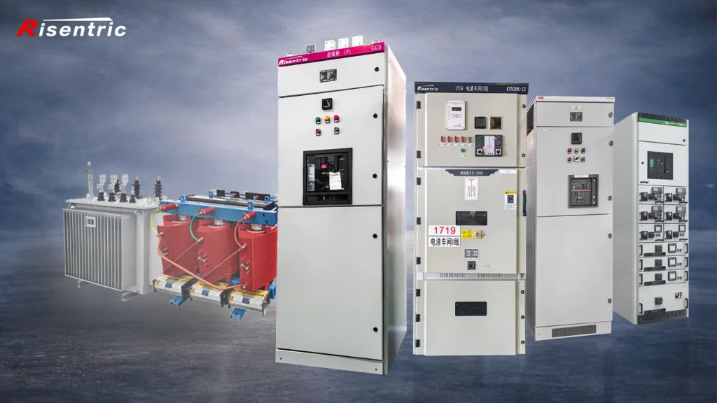
Looking for factory-tested switchgear & Panel boards for your project?
Voltage and Frequency Parameters
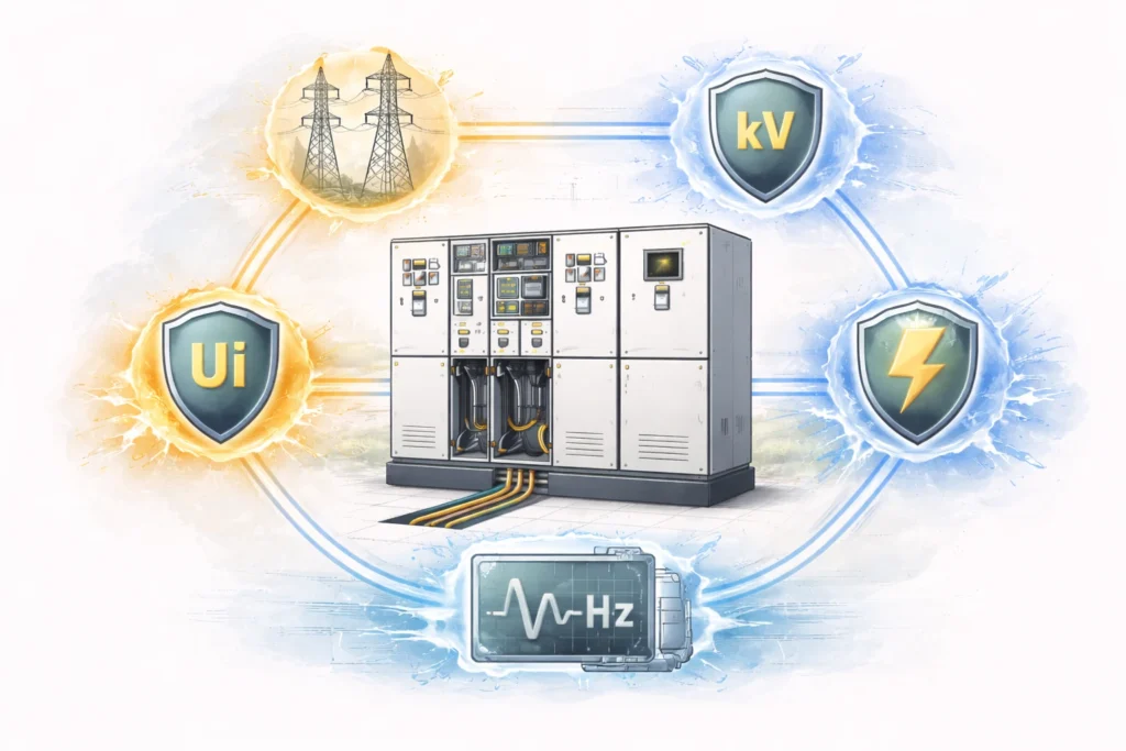
1. System Rated Voltage (Un)
Unit: Volt (V) or kV
Definition:
Un is the nominal rated voltage of the power system at a given point. It defines the voltage class of the electrical network and serves as a reference value for system design, equipment selection, and coordination. Un is a system-level parameter and does not represent the exact operating voltage at all times.
Operating Behavior:
Un does not limit or regulate the actual system voltage and does not trigger any protection. During normal operation, the real voltage may fluctuate above or below Un within the allowable tolerance range of the power system. All connected electrical equipment must have rated operational and insulation voltages equal to or higher than Un to ensure safe and reliable operation.
2. Rated Operational Voltage (Ue)
Unit: Volt (V) or kV
Definition:
Un is the nominal rated voltage of the power system at a given point. It defines the voltage class of the electrical network and serves as a reference value for system design, equipment selection, and coordination. Un is a system-level parameter and does not represent the exact operating voltage at all times.
Operating Behavior:
Un does not limit or regulate the actual system voltage and does not trigger any protection. During normal operation, the real voltage may fluctuate above or below Un within the allowable tolerance range of the power system. All connected electrical equipment must have rated operational and insulation voltages equal to or higher than Un to ensure safe and reliable operation.
3. Rated Insulation Voltage (Ui)
Unit: V or kV
Definition:
Ui is the rated insulation voltage of electrical equipment. It represents the maximum voltage that the insulation system of the equipment can withstand continuously under specified conditions without insulation degradation. Ui is determined by insulation design factors such as air clearance, creepage distance, insulating materials, and internal structure.
Operating Behavior:
Ui is not an operating or protection parameter and does not trigger any protective action. During normal operation, the system voltage (Un) and the equipment rated operational voltage (Ue) must remain below Ui to ensure long-term insulation integrity. If Ui is exceeded, partial discharge, surface creepage, or insulation breakdown may occur, potentially leading to short circuits, equipment damage, or arc faults.
4. Rated Impulse Withstand Voltage (Uimp)
Unit: kV (peak)
Definition:
Uimp is the rated impulse withstand voltage of electrical equipment. It represents the maximum peak value of transient overvoltage, such as lightning impulses or switching surges, that the insulation system of the equipment can withstand for a very short duration without flashover or insulation breakdown.
Operating Behavior:
Uimp applies only to transient conditions and is not related to continuous operation. It does not regulate voltage or initiate protection functions. When impulse overvoltages remain within the Uimp rating, the insulation system maintains its integrity. If Uimp is exceeded, flashover or internal insulation breakdown may occur, potentially causing arc faults, equipment damage, or failure, even if the steady-state voltage remains within Ui and Ue limits.
5. Rated Frequency (fn / f)
Unit: Hertz (Hz)
Definition:
fn (or f) is the rated frequency of the power system for which the electrical equipment is designed to operate continuously under specified normal conditions. It defines the nominal frequency of the AC supply and serves as a reference for equipment design, performance, and thermal characteristics.
Operating Behavior:
When the system frequency remains at or near the rated value fn, the equipment operates normally with its electrical, thermal, and mechanical performance maintained. Moderate frequency deviations are generally permissible for short durations, depending on system standards. Significant or prolonged deviation from fn may lead to increased losses, abnormal heating, reduced efficiency, or malfunction, but fn itself does not provide frequency regulation or protection.
FAQ (Switchgear Parameters Definition)
1) What are “switchgear parameters”?
Switchgear parameters are standardized electrical and mechanical ratings used to select, specify, test, and operate switchgear safely. They describe what the equipment can carry continuously (current), withstand or interrupt during faults (short-circuit ratings), and tolerate electrically (voltage/insulation and impulse levels).
2) What is the difference between In and Inm?
- In (Rated current) is the continuous current the device can carry under specified conditions.
- Inm (Frame size current) is the maximum capability of the breaker frame. It is not a trip value; it defines the upper limit of the trip unit and settings that can be applied to that frame.
3) What is the difference between In and Ir?
- In is the rated continuous current of the device (nameplate rating).
- Ir is the long-time protection setting (overload threshold) of the trip unit. In practice, Ir is adjustable (often expressed as a fraction of In or Inm depending on breaker type).


