
Please note:
This article is intended for readers seeking a deeper engineering explanation of high-current medium-voltage switchgear.
Level: Advanced
This article assumes that 7.2 kV is the switchgear’s rated voltage. If 7.2 kV is the actual nominal system voltage, the required equipment voltage class and insulation level must be confirmed separately.
A 7.2 kV voltage rating is not unusual.
A 6,300 A current rating is technically achievable.
A 63 kA short-circuit rating is also achievable.
However, combining all three ratings in one switchgear system creates an exceptionally difficult engineering problem.
The reason is not simply that the numbers are large. The real difficulty is that the solution for one requirement often makes another requirement harder.
What Do the Four Values Mean?
| Value | What it mainly affects |
|---|---|
| 6,300 A | Continuous heating, conductor size and contact design |
| 7.2 kV | Insulation, electrical clearance and interruption voltage |
| 63 kA | Fault forces, short-time withstand and breaker capability |
| 78.6 MVA | System scale, importance and consequences of failure |
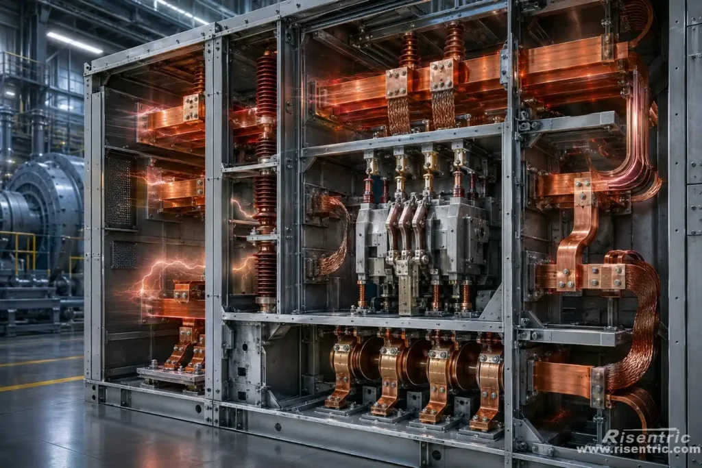
The main structural difficulty comes from combining 6,300 A current-carrying components, 7.2 kV insulation requirements and 63 kA short-circuit strength inside the same switchgear.
Why Is the Combination So Difficult?
The switchgear must be:
- Large enough to carry 6,300 A
- Open enough to remove heat
- Separated enough to withstand 7.2 kV
- Rigid enough to survive 63 kA
- Flexible enough to accommodate thermal expansion
- Fast enough to interrupt a fault
- Closed enough to control an internal arc
These requirements conflict with one another.
That is why a normal 3,150 A or 4,000 A panel cannot simply be converted into a 6,300 A panel by installing larger busbars.
Conflict 1: Large Conductors, Insulation Space and Mechanical Strength
High current wants to fill the switchgear with copper, while medium voltage requires empty insulation space around that copper.
To carry 6,300 A, the switchgear needs large current-carrying components, including:
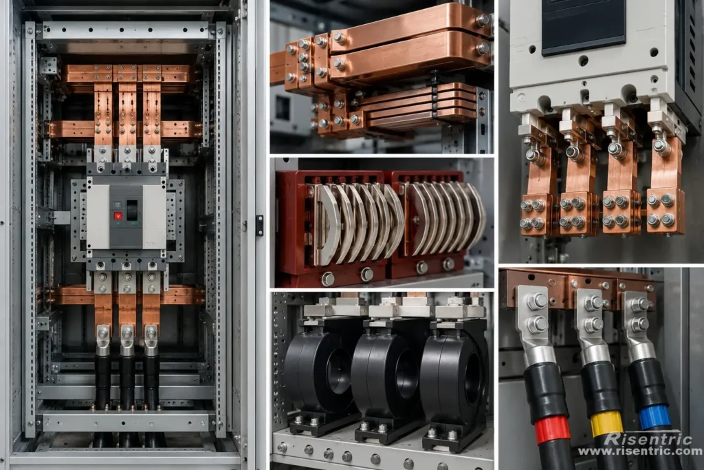
- Multiple busbars in parallel
- Large breaker terminals
- More contact fingers
- Large current transformers
- Large incoming and outgoing connections
At the same time, 7.2 kV equipment must maintain sufficient distance between:
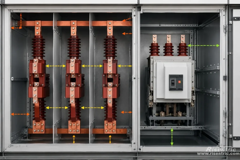
- Phase and phase
- Phase and earth
- Busbars and metal partitions
- Breaker terminals and the enclosure
- Conductors and insulating surfaces
This creates the first fundamental conflict: the conductors become larger, but they cannot simply be packed closely together.
The 63 kA Fault Requires Stronger Support
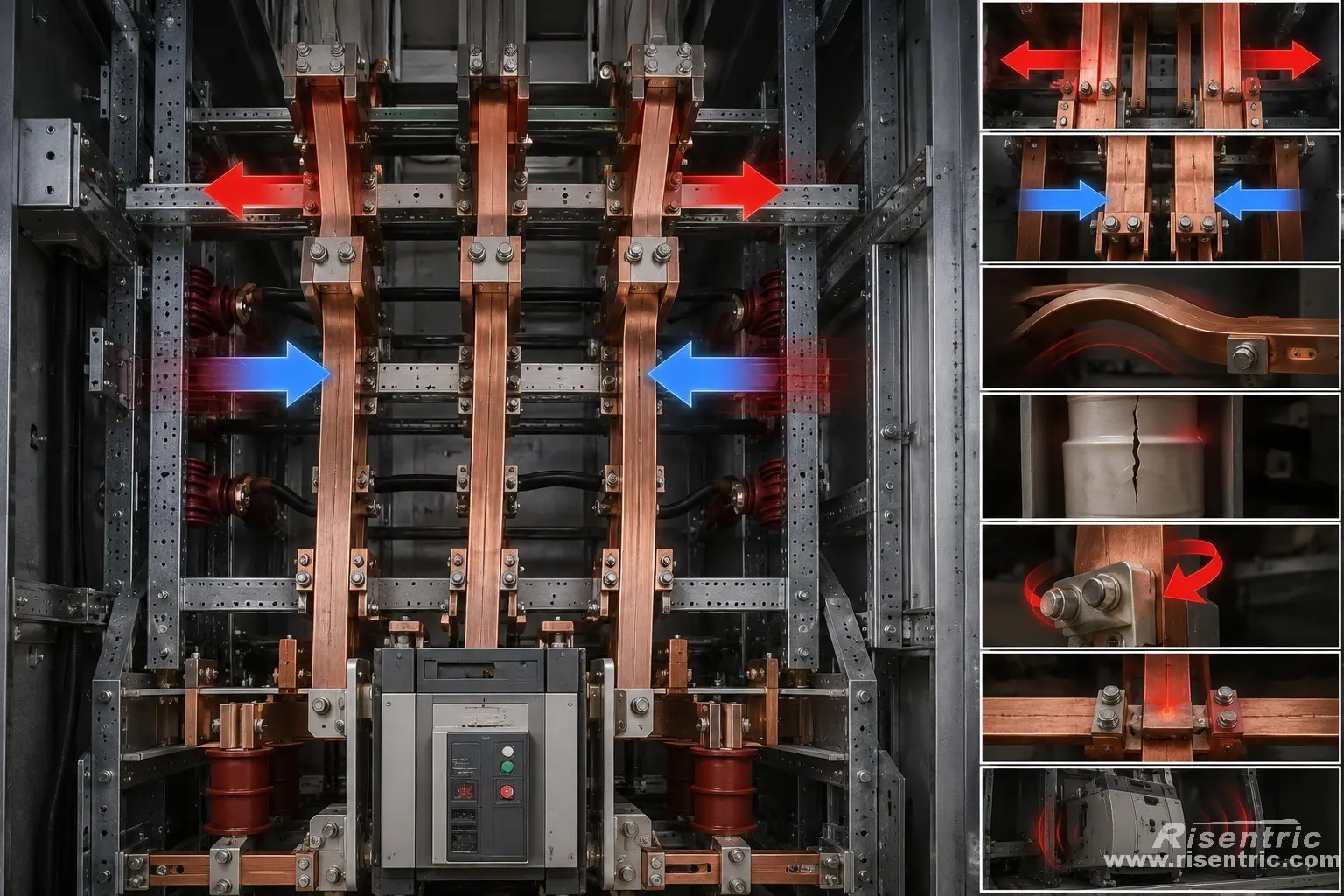
The 63 kA short-circuit requirement makes the arrangement even more difficult.
During a fault, the busbars are exposed to enormous electromagnetic forces. A 63 kA RMS fault may produce a first current peak above 150 kA.
Using a typical peak factor of 2.5:
63 kA × 2.5 = 157.5 kA peak
This instantaneous current can:
- Push phases apart
- Pull parallel busbars together
- Bend conductors
- Crack insulators
- Twist breaker terminals
- Damage joints
- Move the breaker structure
The busbars therefore need strong and closely spaced supports.
The Busbars Must Still Be Able to Expand
Busbars expand as they heat during normal operation. The system may therefore need:
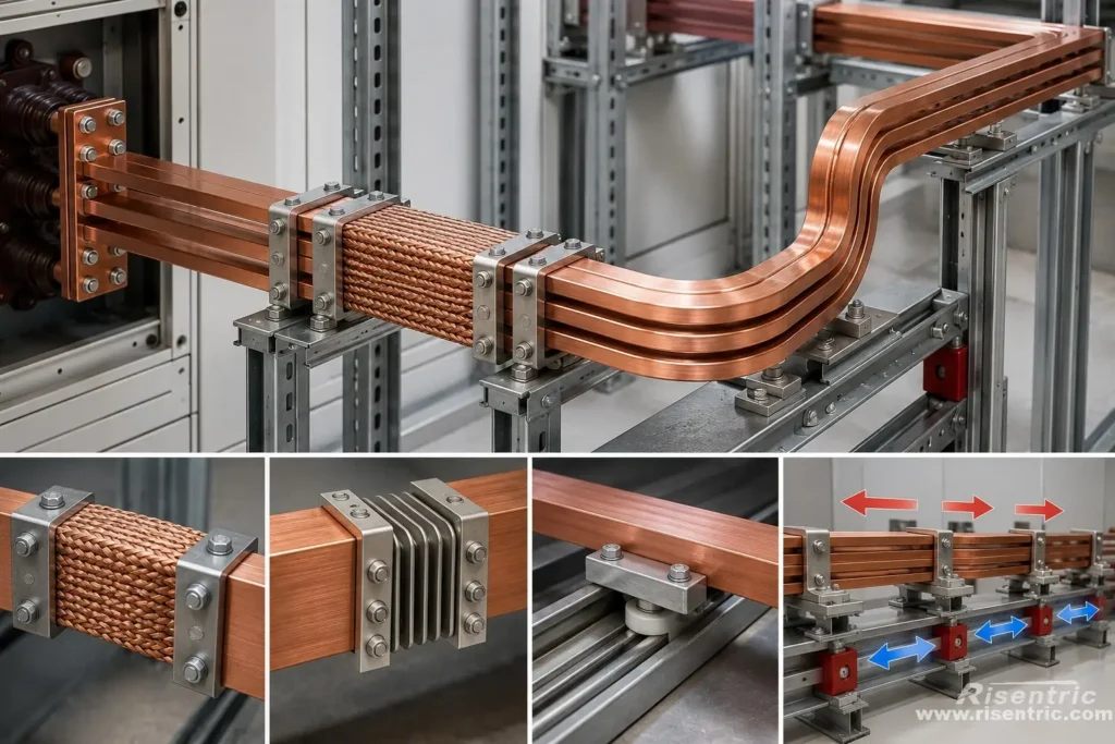
- Flexible copper connections
- Expansion joints
- Sliding supports
- Controlled movement
The structure must allow slow thermal expansion while remaining rigid during a short circuit.
Additional supports improve fault strength, but they also:
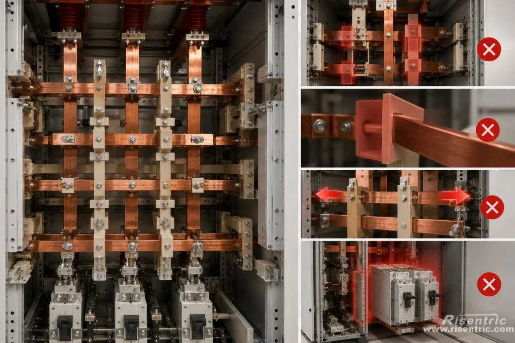
- Occupy valuable compartment space
- Add more insulating surfaces
- Restrict thermal movement
- Make inspection and assembly more difficult
Increasing phase spacing can improve insulation and reduce electromagnetic force, but it also makes the switchgear:
- Wider
- Deeper
- Heavier
- More expensive
- Harder to transport
- Harder to install in an existing switchroom
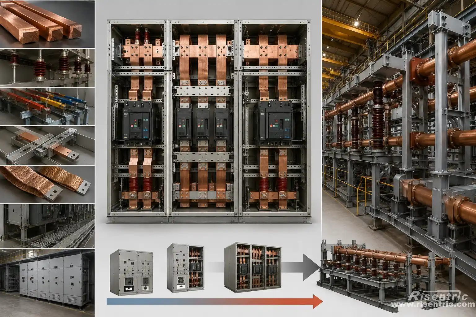
The designer must therefore balance:
- Conductor size
- Insulation clearance
- Phase spacing
- Busbar support spacing
- Thermal expansion
- Maintenance access
- Overall cabinet dimensions
At some point, the equipment may stop resembling conventional metal-clad switchgear and begin to look more like generator switchgear or a power-station bus system.
Conflict 2: Heat Dissipation Versus Enclosure Protection
After the conductors, contacts and supports have been fitted into the switchgear, the next problem is removing the heat they produce.
At 6,300 A, even a very small resistance can generate substantial heat.
Electrical loss in a conductor or connection follows this relationship:
Power loss = Current × Current × Resistance
Suppose one joint has a resistance of only 10 micro-ohms, or 0.00001 ohm.
The heat generated at that joint would be:
6,300 × 6,300 × 0.00001 = 397 W
That means one connection with an extremely low resistance can still produce almost 400 W of heat continuously.
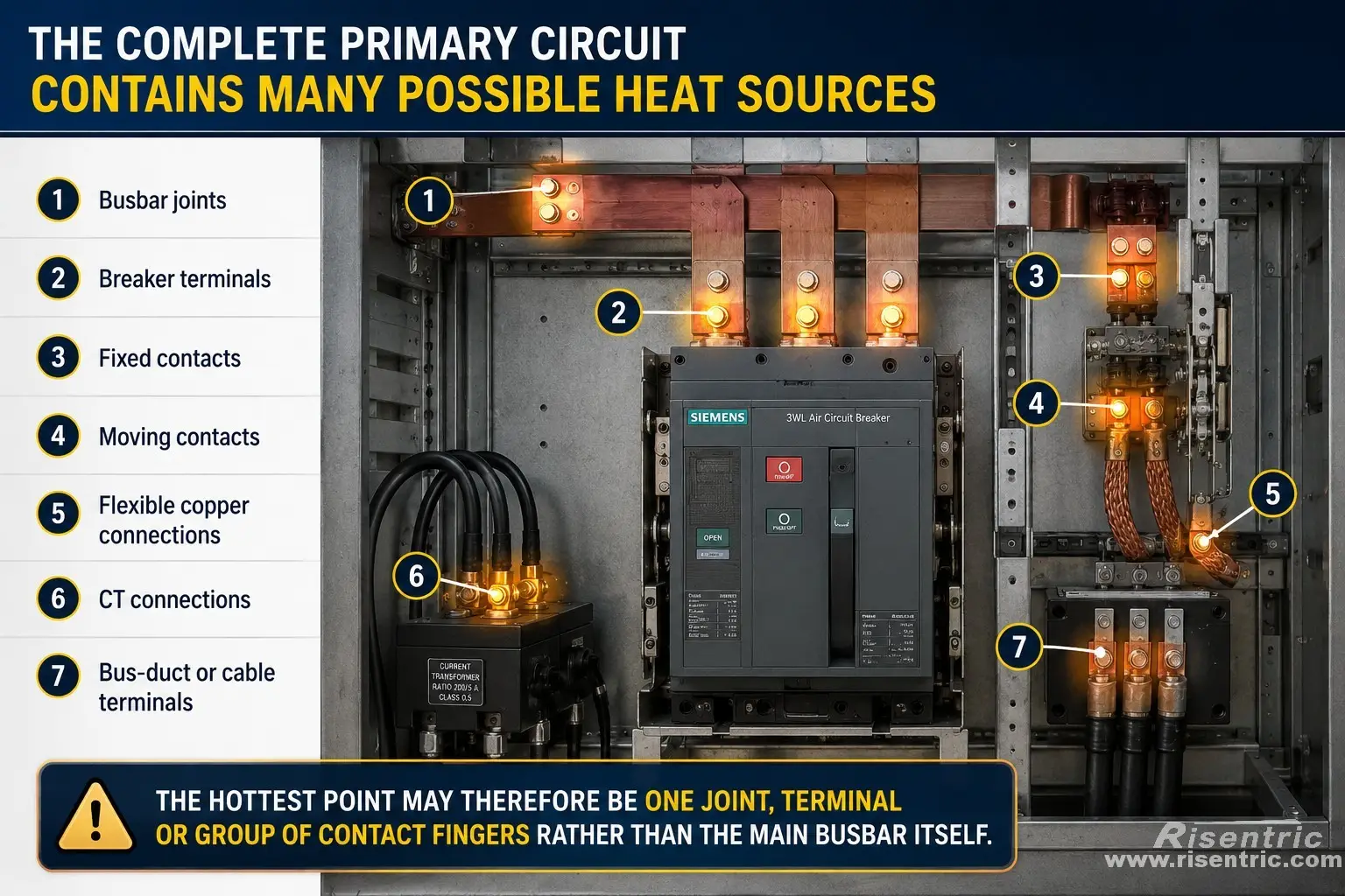
The complete primary circuit contains many possible heat sources:
For effective cooling, the designer may want:
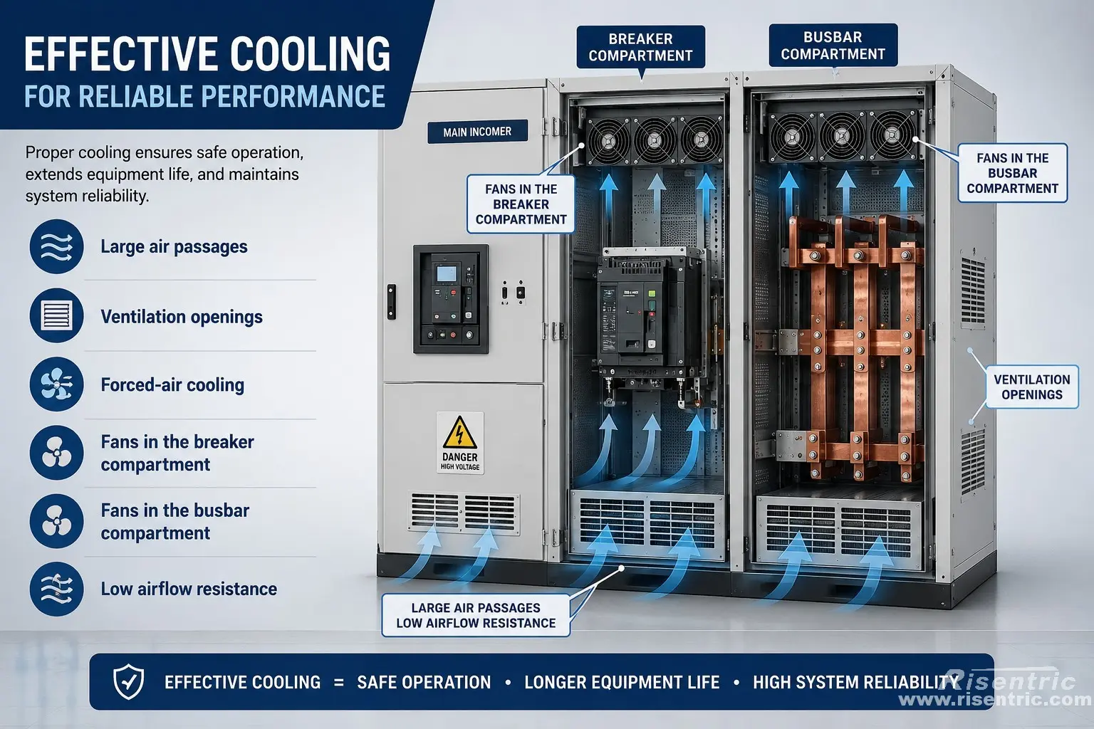
However, internal-arc protection requires a controlled and pressure-resistant enclosure.
The switchgear must:
- Withstand internal pressure
- Keep doors and covers closed
- Prevent flames from escaping toward personnel
- Control the movement of hot gases
- Direct pressure through a safe exhaust path
This creates the second fundamental conflict:
High current requires effective airflow, while internal-arc protection requires controlled and pressure-resistant compartments.
A high IP rating makes the problem harder. A tightly sealed enclosure provides better protection against dust and water, but it also traps heat and restricts airflow.
The manufacturer must therefore balance:
- Temperature rise
- Airflow
- Internal-arc safety
- Environmental protection
- Fan reliability
- Maintenance access
Cooling is not simply a matter of adding fans. The enclosure, ventilation path and pressure-relief system must be engineered together.
Conflict 3: More Parallel Busbars Versus Unequal Current Sharing
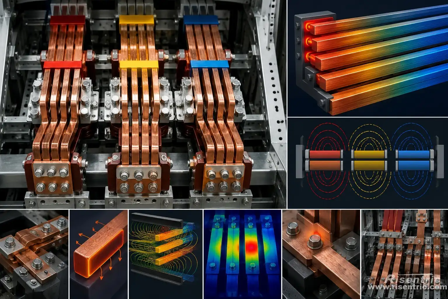
One extremely thick copper bar is not always the best way to carry 6,300 A.
High-current systems normally use several parallel conductors for each phase.
For example, if four busbars share the current equally:
6,300 A ÷ 4 = 1,575 A per busbar
However, the current may not divide equally in practice.
Current sharing is affected by:
- Different conductor lengths
- Unequal joint resistance
- Skin effect
- Proximity effect
- Busbar position
- Magnetic fields from nearby phases
- Unequal cooling
- Different contact pressure
One conductor may carry more current than the others and become a local hotspot.
Adding more copper reduces basic resistance, but it also makes AC current distribution and electromagnetic behaviour more complicated.
The design must therefore consider the complete three-phase busbar arrangement, not only the total copper cross-sectional area.
Conflict 4: Low Contact Resistance Versus Withdrawable Construction
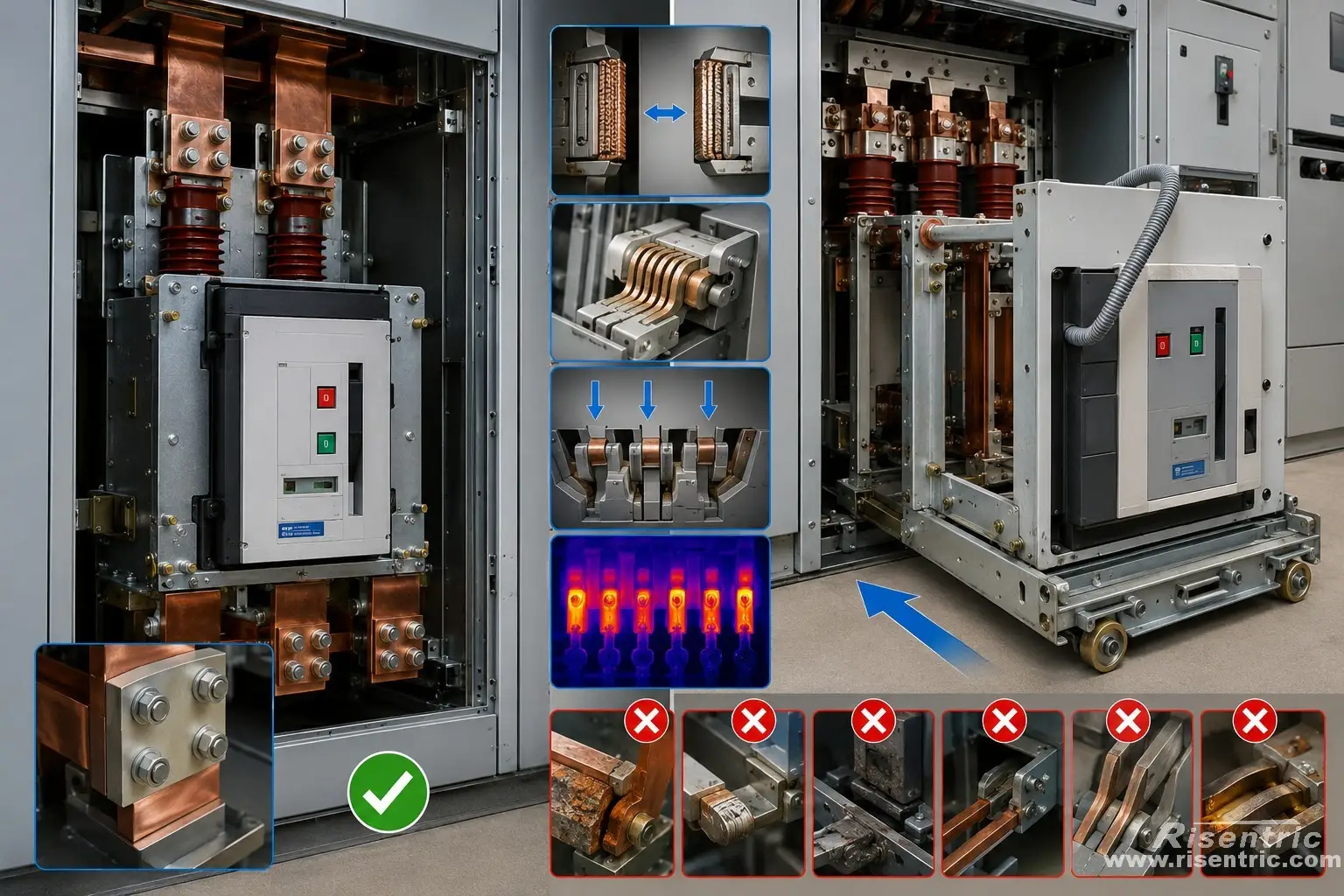
A fixed bolted connection can be made large, strong and highly conductive.
A withdrawable breaker is much more difficult.
Its primary contacts must be:
- Movable
- Accurately aligned
- Low resistance
- Mechanically durable
- Properly insulated
- Able to carry 6,300 A continuously
- Able to withstand the short-circuit peak
The designer may add more contact fingers and increase their pressure to reduce resistance.
But this creates:
- Greater insertion force
- A heavier breaker truck
- More mechanical wear
- Higher alignment sensitivity
- More difficult maintenance
- Greater risk of unequal current sharing
If some contact fingers lose pressure, the remaining contacts may carry excessive current and overheat.
For this reason, a fixed-mounted breaker with separate disconnectors may be more practical than a conventional withdrawable VCB.
Looking for factory-tested 3-Phase switchgear & Panel boards for your project?
The Breaker May Be the Real Bottleneck
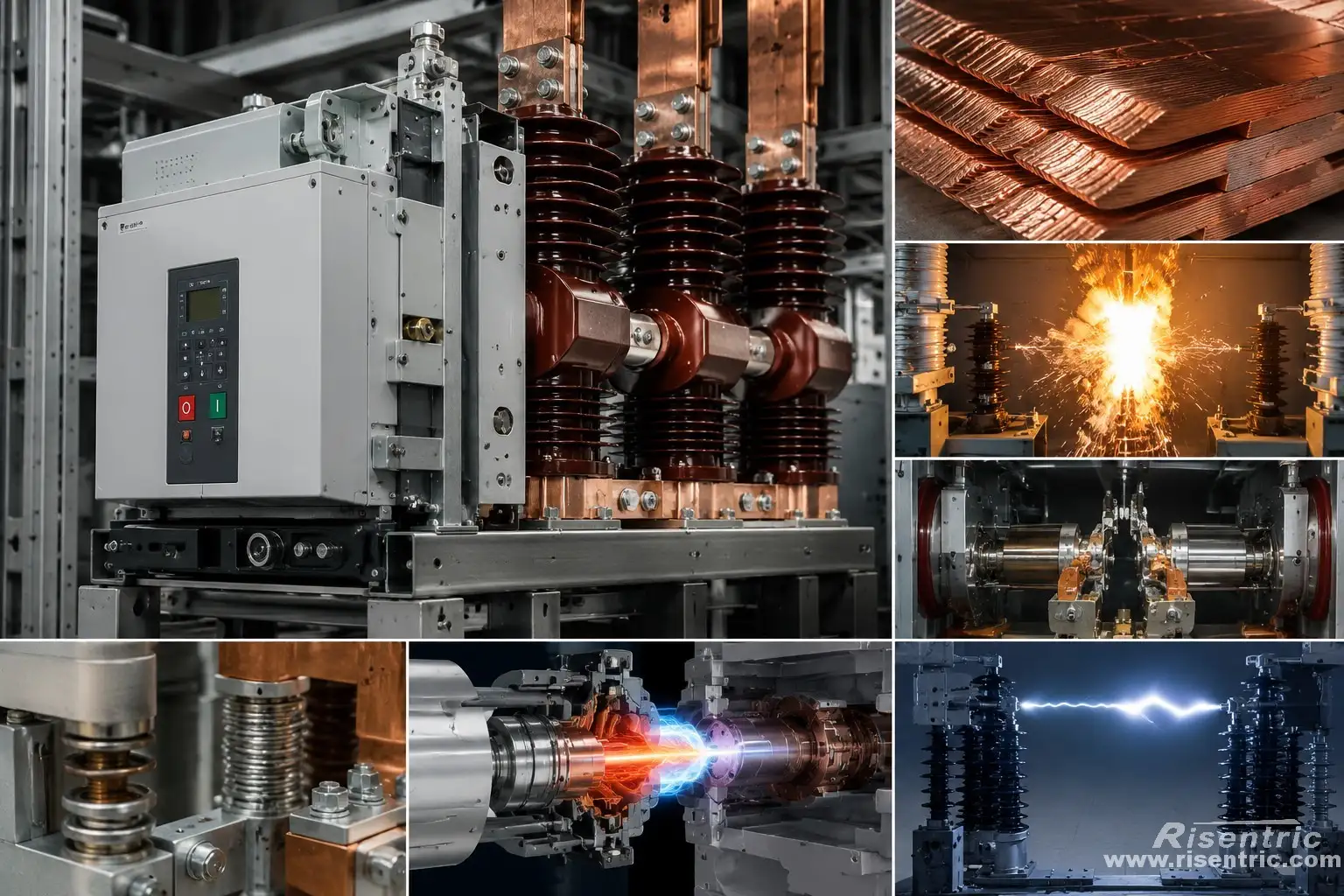
Large copper busbars can be manufactured.
The more difficult question is whether the breaker can:
- Carry 6,300 A continuously
- Remain stable during the first fault-current peak
- Open quickly when protection operates
- Interrupt 63 kA safely
- Withstand the voltage that recovers across the open contacts
- Maintain the required 7.2 kV insulation level
The breaker requires low resistance and high contact pressure during normal operation.
During a fault, it must also open quickly and interrupt an extremely high current.
It must therefore be strongly closed, mechanically stable and capable of rapid opening at the same time.
A normal 4,000 A breaker cannot usually become a 6,300 A breaker simply by fitting larger external terminals.
The complete internal current path must be designed and tested for 6,300 A.
About power
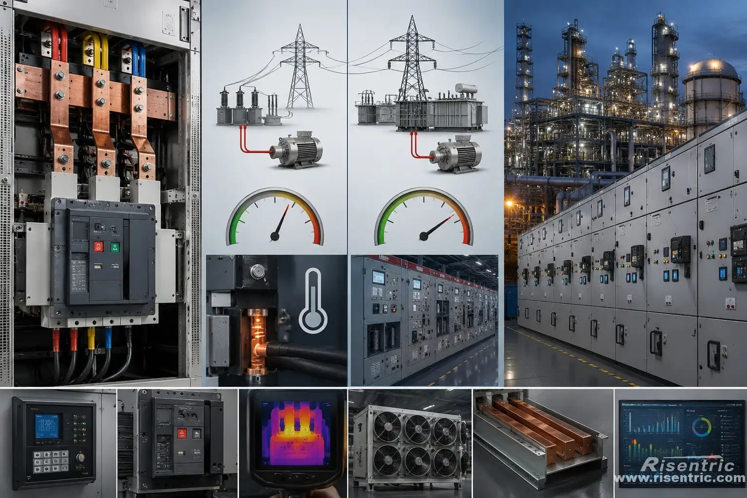
At 400 V and 6,300 A, the three-phase apparent power is approximately 4.36 MVA:
1.732 × 0.4 kV × 6.3 kA = 4.36 MVA
At 7.2 kV and the same current, the apparent power rises to approximately 78.6 MVA:
1.732 × 7.2 kV × 6.3 kA = 78.6 MVA
The 7.2 kV circuit therefore transfers about 18 times as much apparent power.
The higher power does not directly make the conductors hotter. If the current and conductor resistance are the same, the resistive losses are also similar.
However, the 78.6 MVA rating shows the scale of the system. One circuit may be connected to a large generator, transformer, compressor system or industrial process. A failure or unnecessary trip could therefore disconnect tens of megawatts of load.
This may require:
- High-speed and reliable protection
- Differential and breaker-failure protection
- Continuous temperature monitoring
- Reliable cooling
- Large bus-duct connections
- More extensive condition monitoring
How Internal-Arc Protection Changes the Enclosure
Internal-arc protection is not the original reason the switchgear needs larger busbars. However, once the 7.2 kV, 6,300 A current path has been designed, arc containment creates another major structural requirement.
During normal operation, the switchgear carries up to 6,300 A. If an insulation failure, loose connection or foreign object creates an internal fault, the current may rise toward the available short-circuit level—in this case, 63 kA.
The three ratings contribute differently:
| Rating | Effect during an internal fault |
|---|---|
| 6,300 A | Requires large conductors, contacts, joints and cooling paths |
| 7.2 kV | Allows an arc to remain established across an air gap |
| 63 kA | Determines the available fault current and potential severity of the event |
An internal arc creates gas plasma at approximately 10,000°C, with local temperatures reaching up to 20,000°C near the arc outlet. These are local plasma temperatures, not the average temperature inside the complete switchgear. At the arc location, metal and nearby insulation may melt or vaporize almost immediately.
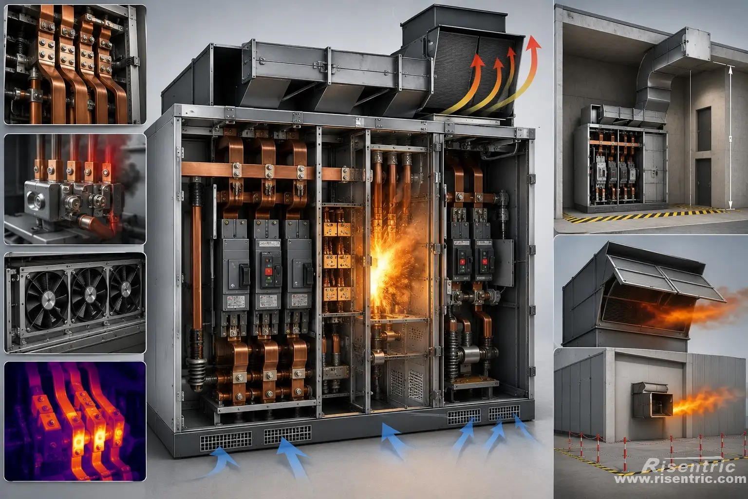
The rapidly heated gas and vaporized material cause a sharp pressure rise. The switchgear may therefore require:
- Reinforced doors and locking systems
- Pressure-resistant internal partitions
- Pressure-relief flaps
- An overhead exhaust plenum
- External pressure-relief ducts
- A controlled discharge area away from personnel
The electrical room must also be considered. Siemens notes that medium-voltage switchrooms may require pressure-relief outlets or ducts, and that the building structure may need to withstand the pressure generated by an internal arc.
This creates another design conflict:
The 6,300 A current path requires effective cooling during normal operation, while internal-arc protection requires controlled, pressure-resistant airflow during a fault.
The ventilation and pressure-relief systems must therefore be engineered together. Normal cooling openings cannot simply be allowed to release flames or hot gases toward personnel.
A 63 kA Arc-Resistant Switchgear Example
The amount of additional installation space depends on the tested switchgear platform. There is no universal rule stating that arc-resistant construction adds a fixed height or percentage to every panel.
For reference, ABB’s SafeGear HD is a specific 5/15 kV, 63 kA arc-resistant switchgear platform that uses an overhead pressure-relief plenum. ABB specifies a minimum floor-to-ceiling distance of approximately 129.5 inches, or 3.29 metres, for the plenum arrangement and vent-box clearance.
This figure is only a real-product example. It should not be treated as the required room height for every 7.2 kV, 6,300 A design.
A 6,300 A system may require a different:
- Base-panel height
- Cooling arrangement
- Plenum size
- Exhaust-duct cross-section
- Safe discharge area
- Switchroom ceiling height
The exact dimensions must come from the manufacturer’s tested general arrangement.
The important point is:
Internal-arc protection may add substantial overhead space, exhaust ducting, structural reinforcement and switchroom requirements, but the amount is specific to the tested equipment design.
The Connections Can Become Another Major Problem
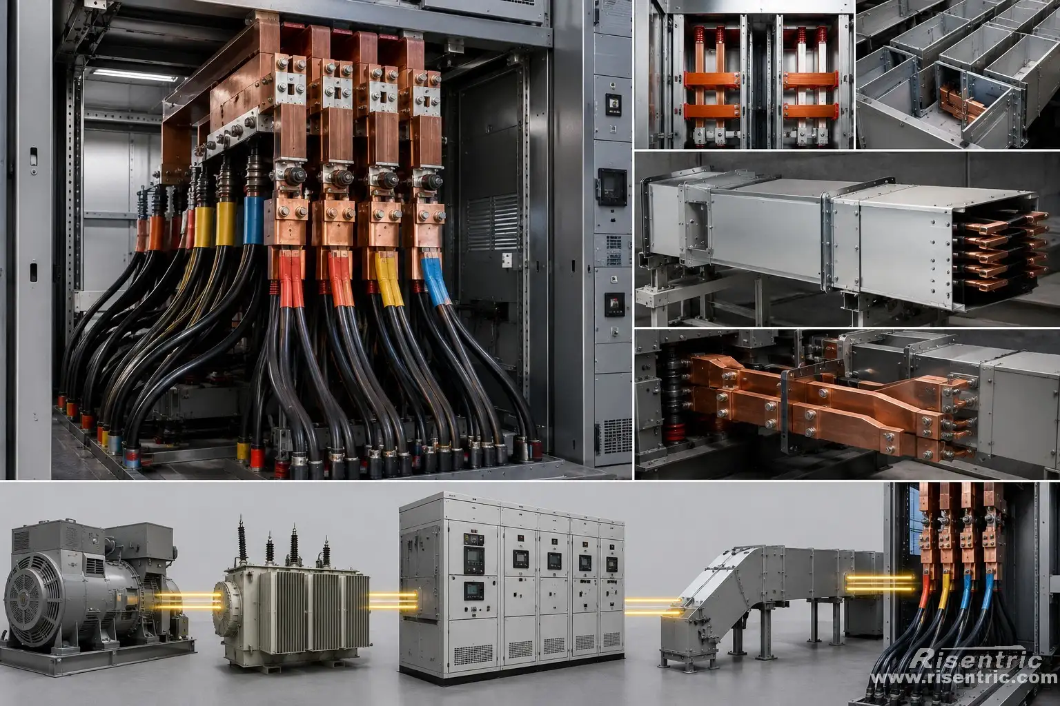
At 6,300 A, ordinary medium-voltage cable connections may become impractical.
The system may require:
- Many parallel cables per phase
- Segregated-phase bus duct
- Non-segregated bus duct
- Direct copper-bar connection
- Isolated-phase bus in generator applications
The connection system must also handle:
- Equal current sharing
- Thermal expansion
- 7.2 kV insulation
- 63 kA fault force
- Mechanical alignment
- Structural support
- Ventilation
The switchgear cannot be designed separately from the generator, transformer or bus duct connected to it.
The complete current path must be coordinated as one system.
More Practical Alternatives
Before selecting one 6,300 A bus, the system designer should consider whether the load can be divided.
Divide the System into Lower-Current Bus Sections
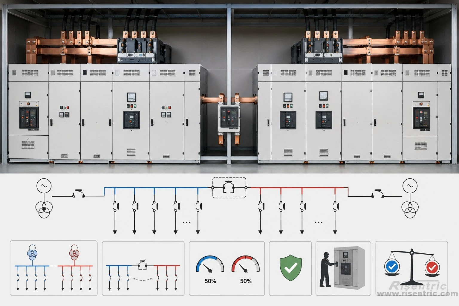
Instead of using one 6,300 A bus, the system can be divided into two independent bus sections.
Possible arrangements include:
- Two 3,150/4,000 A bus sections
- Separate transformer or generator incomers for each section
- A normally open bus coupler between the sections
This allows each section to remain within a more established medium-voltage switchgear range.
A two-section arrangement can provide:
- More widely available breakers
- Easier temperature-rise control
- Smaller busbars and connections
- Easier maintenance
- Better redundancy
- Lower technical and testing risk
However, the ratings should not simply be added.
Two 3,150 A sections do not form one 6,300 A bus unless their outputs are combined. If they are combined through one bus coupler or common connection, that part of the system may still need to carry the full 6,300 A.
The practical solution is normally to divide the loads between the two sections and keep the bus coupler normally open. The coupler can then be closed temporarily for load transfer, provided the remaining source and bus section can carry the transferred load.
Distribute the Power at a Higher Voltage
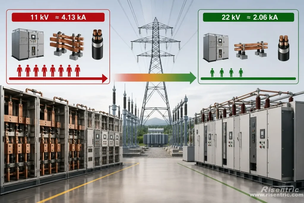
For the same power, increasing voltage reduces current.
For example, transmitting 78.6 MVA at 11 kV would require approximately 4,130 A.
The calculation is:
78.6 MVA ÷ 1.732 ÷ 11 kV = approximately 4.13 kA
At 22 kV, the same power would require approximately 2,060 A.
The calculation is:
78.6 MVA ÷ 1.732 ÷ 22 kV = approximately 2.06 kA
Increasing the distribution voltage can greatly simplify:
- Busbars
- Breakers
- Connections
- Cooling
- Mechanical supports
However, it also increases the required insulation level.
Use a Generator Circuit-Breaker System
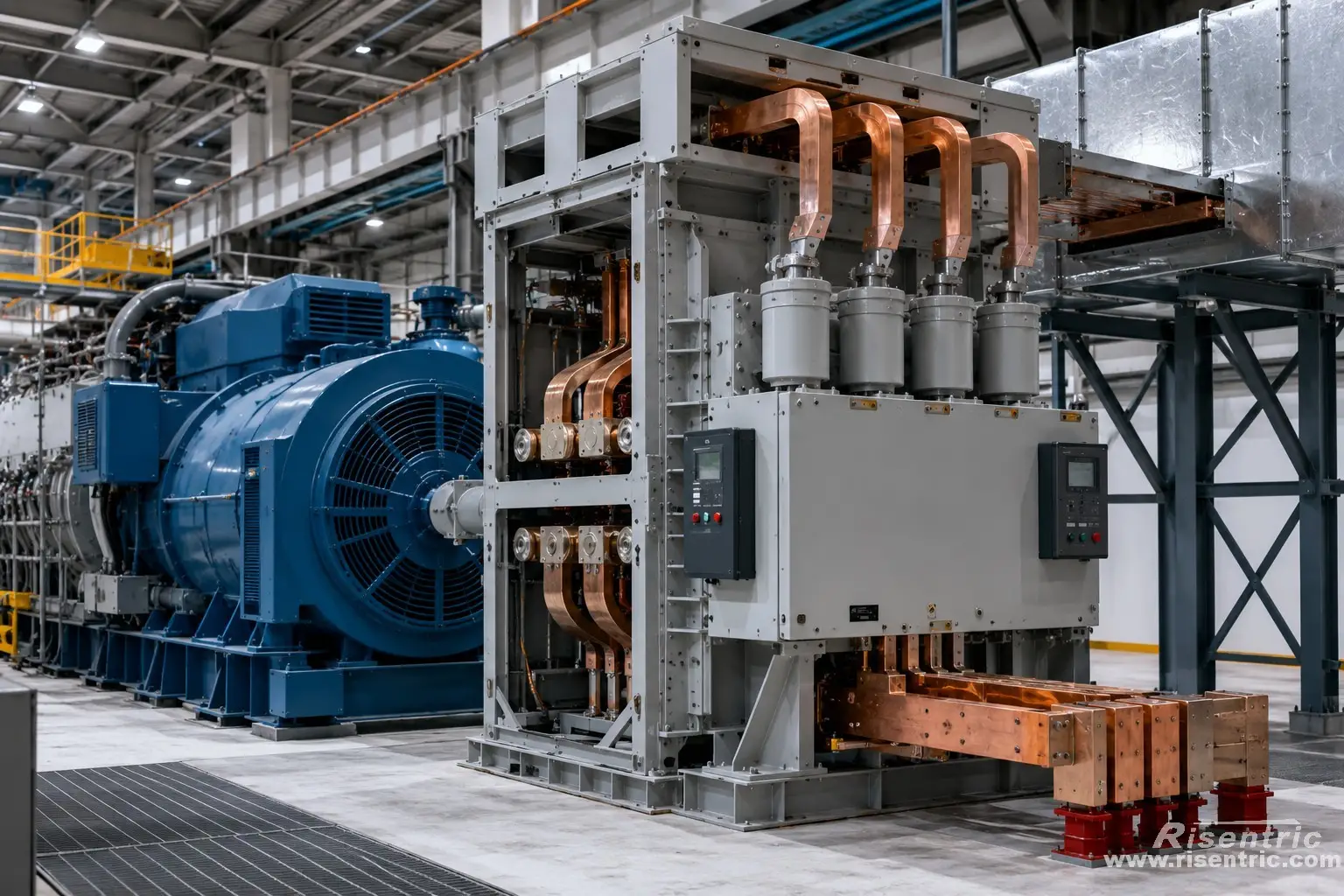
If the circuit is directly connected to a large generator, dedicated generator equipment may be more appropriate than modifying conventional distribution switchgear.
Generator circuit breakers are specifically designed for:
- Very high continuous current
- High short-circuit current
- Severe interruption duty
- Generator-source fault behaviour
- Large bus-duct connections
Looking for factory-tested 3-Phase switchgear & Panel boards for your project?
Conclusion
A 7.2 kV, 6,300 A and 63 kA switchgear system is difficult because the requirements work against one another.
- 6,300 A requires more copper and more cooling.
- 7.2 kV requires more insulation space.
- 63 kA requires stronger and more rigid supports.
- Thermal expansion requires controlled flexibility.
- Internal-arc safety requires a strong, pressure-managed enclosure.
- Breaker operation requires both high contact pressure and rapid opening.
The central challenge is not simply building a larger cabinet.
It is creating a system that is simultaneously:
Electrically insulated, thermally stable, mechanically strong, operationally fast and safe during an internal fault.
That is why this combination normally belongs to specialized generator or heavy-industrial equipment rather than conventional medium-voltage switchgear.
Frequently Asked Questions
Is 7.2 kV, 6,300 A switchgear impossible to manufacture?
No. It is technically achievable, but it normally requires specialized generator-class or custom high-current equipment rather than conventional MV switchgear.
Why is 6,300 A easier at low voltage?
Low-voltage switchgear requires much smaller insulation clearances. Large busbars, breakers and parallel contacts can therefore be installed closer together.
Can larger copper busbars solve the problem?
No. Larger busbars may reduce heating, but they do not solve breaker capacity, insulation clearance, contact resistance, cooling, CT size or 63 kA fault forces.
What does the 63 kA rating affect?
It affects the breaker’s fault capability and the mechanical strength required for busbars, supports, terminals and the enclosure.
Is internal-arc protection the main difficulty?
It is an important personnel-safety requirement, but the main structural challenge is combining 6,300 A conductors, 7.2 kV insulation distances and 63 kA short-circuit strength.
Is dividing the bus a practical alternative?
Yes. Dividing the loads between two lower-current bus sections can allow the use of more established switchgear platforms. However, any common connection must still be rated for the current it actually carries.
Reference:
https://library.e.abb.com/public/c379d6ff07f045eca0d55e4616d080fc/1VAL108001-TG_RevD_SafeGearHD-techguide_DIGITAL.pdf?x-sign=Uh%2BO2i6Dp%2BHKyRv5%2BauCw0CnChCsbvywF6%2Flmqwb2NXE9RS3Le0yF9lKYaDOXROt
https://support.industry.siemens.com/cs/document/109972296/air-insulated-medium-voltage-switchgear-type-nxair-50-ka?dti=0&lc=en-GB


