
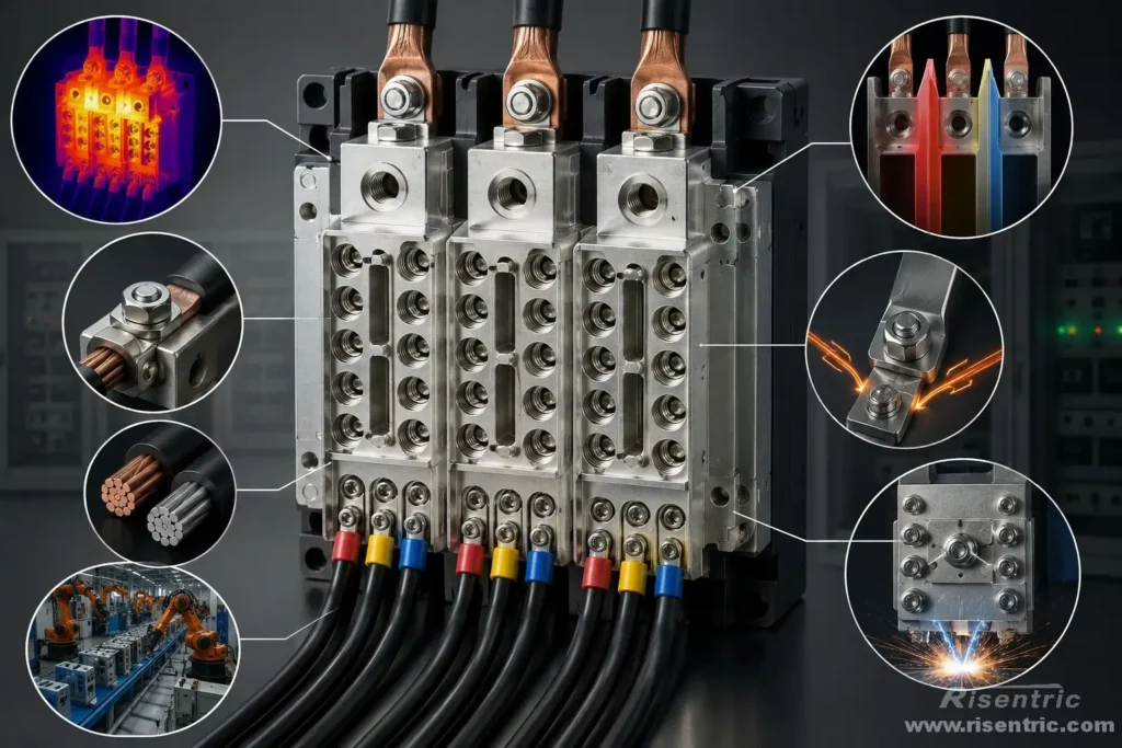
A power distribution block may look like a simple piece of metal with several cable openings.
However, when it carries 600 A or more, its design becomes much more demanding. The manufacturer must control:
- conductor heating
- terminal contact resistance
- cable-clamping pressure
- insulation between phases
- short-circuit forces
- copper and aluminium compatibility
Square D 9080LBA365212
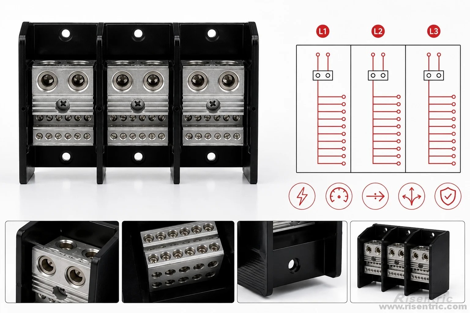
This article explains the design principles of high-current power distribution blocks. The Square D 9080LBA365212 will be used as the primary example throughout the article.
It is a three-pole distribution block with two incoming terminals and twelve outgoing terminals per phase.
Its published ratings include:
| Item | Rating |
|---|---|
| Rated voltage | 600 V AC/DC |
| Current with copper conductors | 760 A |
| Current with aluminium conductors | 620 A |
| Incoming terminals | 2 per phase |
| Outgoing terminals | 12 per phase |
| Number of poles | 3 |
Its main value is not circuit protection. It provides a compact, documented and repeatable way to divide a large feeder into multiple smaller conductors.
Why Do We Need a Power Distribution Block?
The basic purpose of a power distribution block is to divide one large incoming feeder into several smaller outgoing connections.
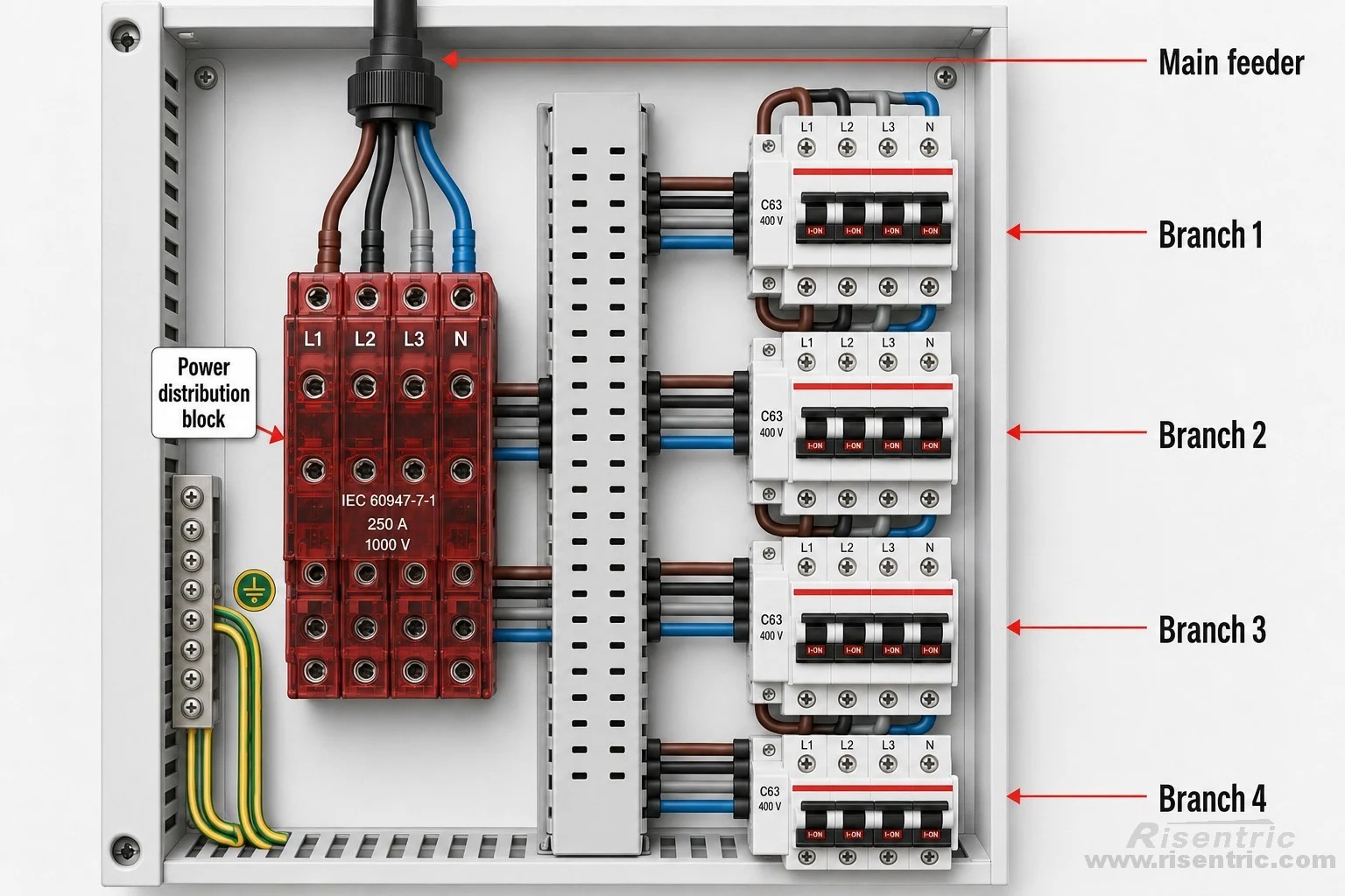
Without a distribution block, the panel builder may need to:
- connect several conductors to one breaker terminal
- manufacture a custom copper busbar
- install many separate cable lugs
- add insulating supports and phase barriers
- create more joints inside the panel
- use more cabinet space
A properly selected distribution block provides factory-made conductor openings, defined tightening torque, insulation between phases and documented electrical ratings.
It is especially useful when the power must be divided in one concentrated area of the panel.
Distribution Block vs Busbar
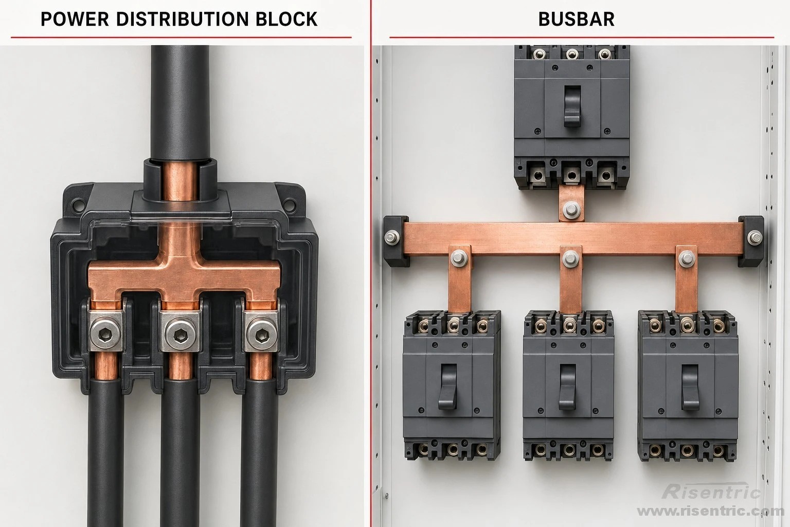
You may wonder, why not use busbar instead.
| Design Consideration | Power Distribution Block | Busbar |
|---|---|---|
| Best application | Local branching from one feeder | Panel-wide power distribution |
| Typical outgoing circuits | Several smaller cable branches | Multiple medium- or high-current feeders |
| Installation | Fast, compact and standardized | Requires fabrication, supports and bolted connections |
| Connection layout | Fixed number and size of terminals | Highly customizable |
| Future expansion | Limited by spare terminals | Easier to design with expansion capacity |
| Heat dissipation | More concentrated | Generally better |
| Current and fault capacity | Limited by the product rating and SCCR | Better suited to very high current and high fault levels |
| Certification | Published ratings and UL documentation may be available | Normally verified as part of the complete switchboard |
| Main advantage | Convenience and documented performance | Capacity, flexibility and panel-wide distribution |
A distribution block is usually better for compact, localized cable branching. A busbar is usually better when power must be distributed across many breakers or cabinet sections.
Looking for factory-tested 3-Phase switchgear & Panel boards for your project?
The Internal Design Concept
A power distribution block can be understood as a short insulated busbar with multiple cable terminals.
For example, the Square D 9080LBA365212 has three separate phase poles. Each pole has two large incoming terminals connected to twelve smaller outgoing terminals through a common conductive body.
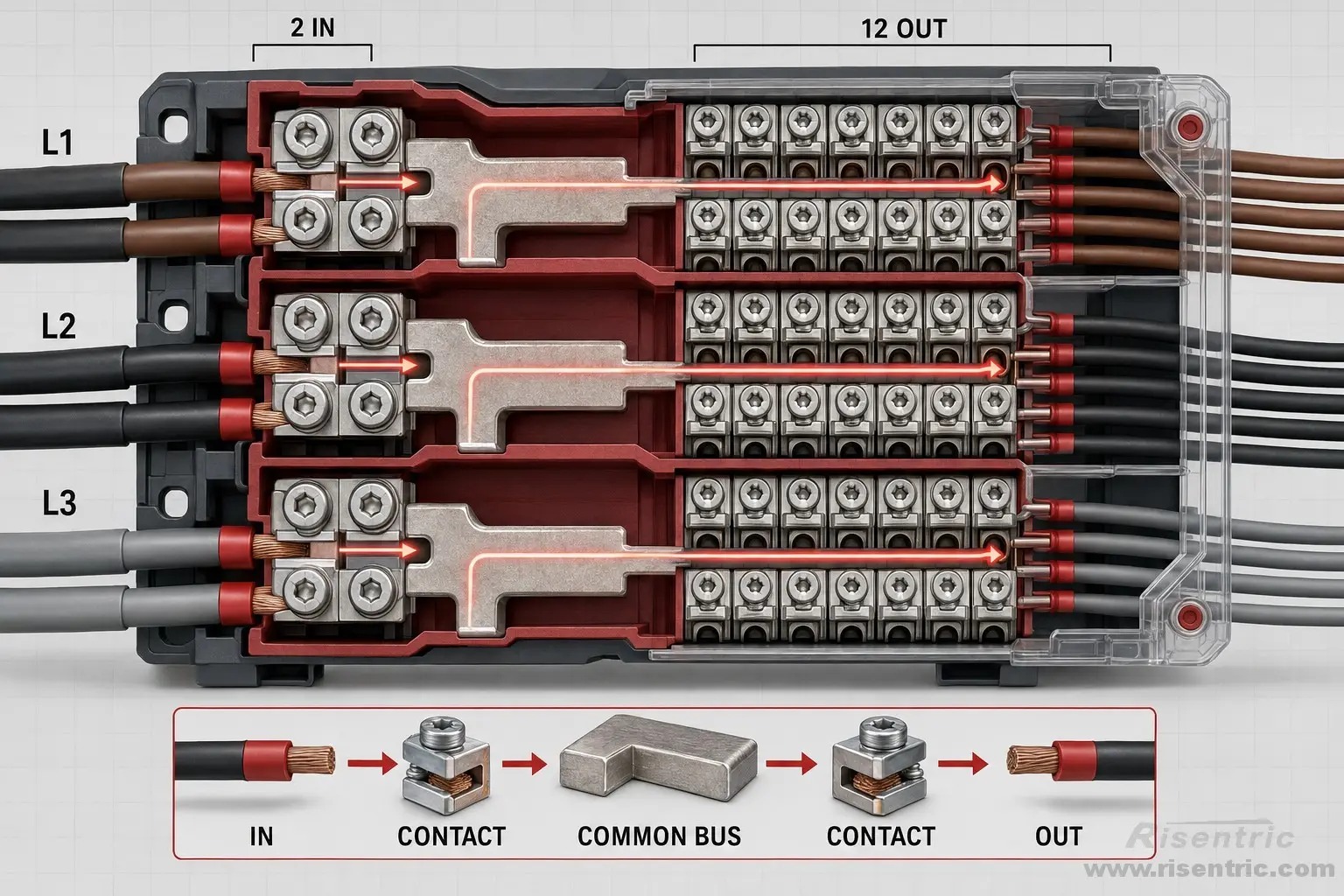
The current path is:
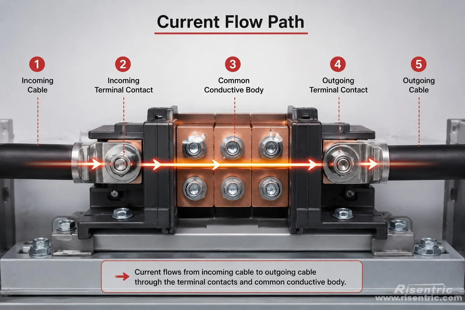
Incoming cable → incoming terminal contact → common conductive body → outgoing terminal contact → outgoing cable
There are no sensors, moving contacts or trip mechanisms inside a standard distribution block. It only carries and divides the current.
How Does Current Divide Through the Block?
The common conductive body carries the combined current supplied to all outgoing branches on that phase.
The outgoing currents do not need to be equal. One branch may carry 80 A, another 100 A, and another only 60 A.
For example, consider a three-pole distribution block with a rated current of 760 A per phase pole when used with copper conductors, such as the Square D 9080LBA365212:
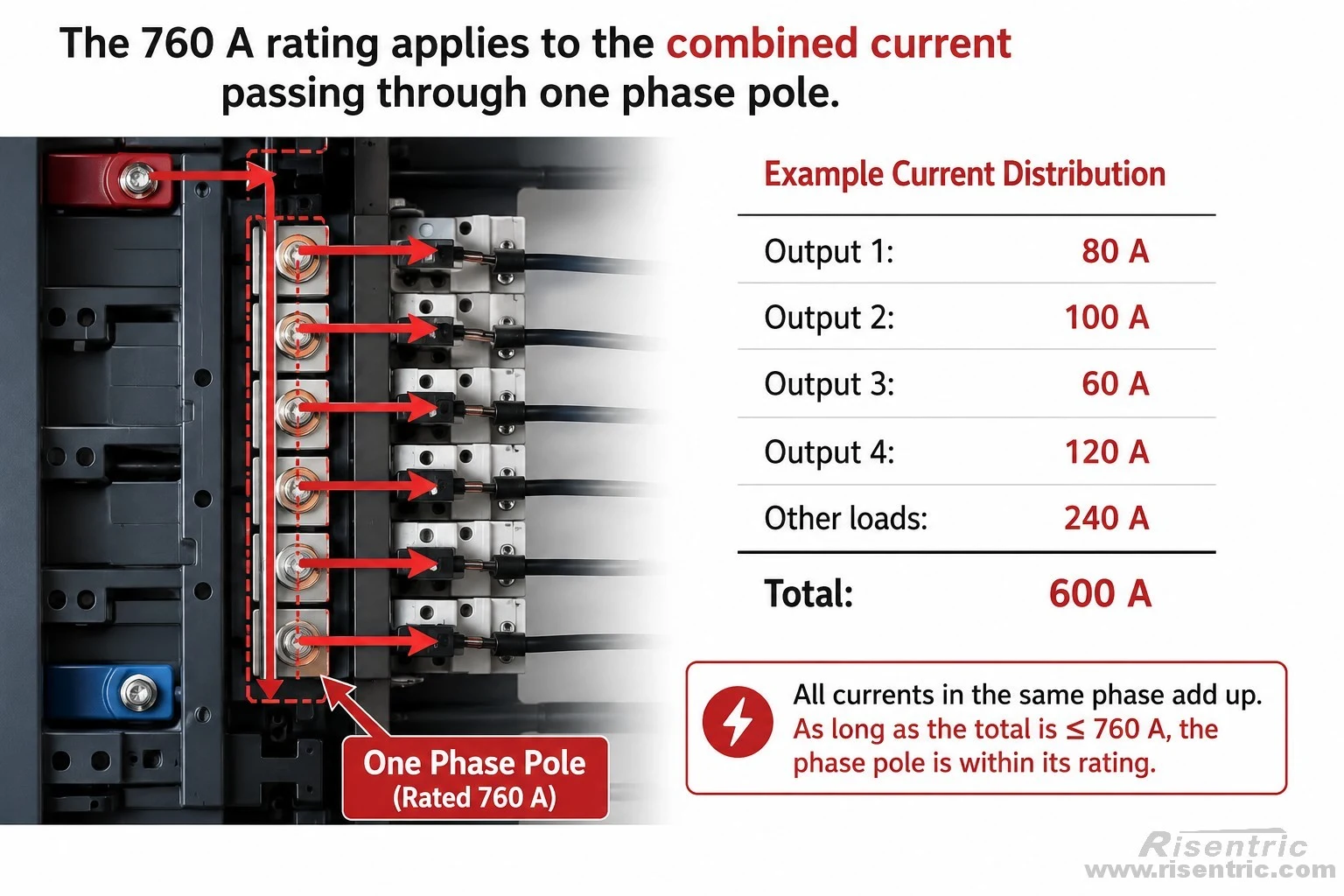
The total current through the phase pole is therefore:
80 A + 100 A + 60 A + 120 A + 240 A = 600 A
Also, for a distribution block rated at 760 A, this represents:
600 A ÷ 760 A ≈ 79% of the phase-pole rating
As current leaves through each outgoing terminal, the current remaining in the common conductor decreases:
Before the first branch: 600 A
After one 50 A branch: 550 A
After two 50 A branches: 500 A
After three 50 A branches: 450 A
The exact current distribution depends on the internal shape of the block and the positions of the connected branches. However, the section carrying the combined branch current normally experiences the highest electrical and thermal stress.
Does Higher Current Simply Require Thicker Metal?
A larger conductive cross-section is important, but thickness alone does not determine the current rating.
The resistance of the conductive path depends approximately on:
Resistance = Material resistivity × Conductor length ÷ Cross-sectional area
A larger cross-sectional area reduces resistance, voltage drop and heat generation.
However, the rated current of a distribution block depends on the entire current path, including:
- short-circuit mechanical strength
- the conductive material
- terminal contact area
- clamping pressure
- heat dissipation
- insulation temperature limits
Contact Area
The cable must make sufficient contact with the terminal surface.
A small or uneven contact area concentrates the current into a smaller region, increasing local resistance and heat.
Clamping Pressure
The terminal screw must maintain stable pressure despite:
- vibration
- thermal expansion
- repeated heating and cooling
- long-term conductor creep
If the pressure decreases, contact resistance may increase and the terminal can overheat even when the total current remains below the block rating.
Conductive Material and Plating
The conductive alloy and surface plating affect:
- conductivity
- oxidation resistance
- corrosion resistance
- copper and aluminium compatibility
- long-term contact stability
For this reason, a high-current distribution block cannot be designed only by selecting a large piece of metal.
Heat Dissipation
Heat leaves the block through:
- the conductive body
- connected cables
- surrounding air
- mounting structure
- panel enclosure
The same block may operate at different temperatures depending on its installation.
For example, it will normally run hotter inside a sealed IP65 cabinet than in an open or well-ventilated enclosure.
Mechanical Strength
During a short circuit, the conductors create strong electromagnetic forces.
These forces may pull on the cables, terminal screws and conductive body. The insulating base and terminal structure must remain secure until the upstream fuse or breaker clears the fault.
The internal design must therefore balance:
- sufficient conductive cross-section
- low contact resistance
- reliable clamping pressure
- heat dissipation
- phase insulation
- short-circuit mechanical strength
A high-current power distribution block is not simply made by using thicker metal. Its rating depends on the complete current path, from the incoming cable connection to the common conductor and every outgoing terminal.
About Terminals
Why Are Terminal Connections Critical?
The conductive body normally has very low resistance.
The highest-risk areas are often the cable-to-terminal connections.
Electrical heating follows this approximate relationship:
Power loss = Current² × Resistance
This means that even a small increase in terminal resistance can create significant heating at high current.
For example:
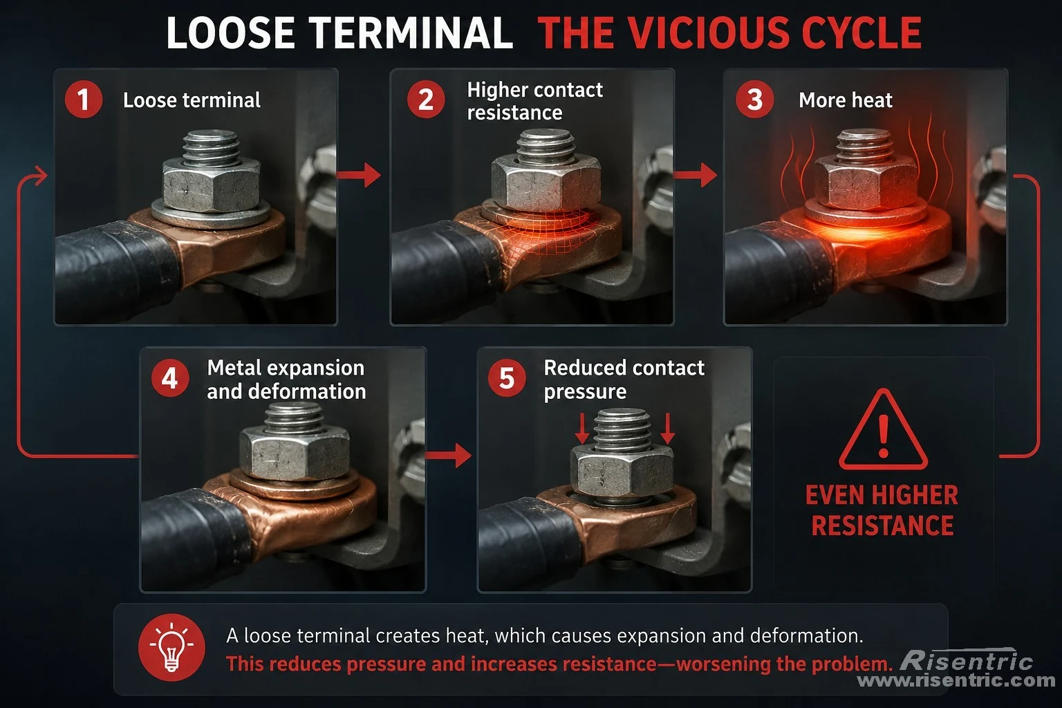
Loose terminal → higher contact resistance → more heat → metal expansion and deformation
→ reduced contact pressure → even higher resistance
This can become a self-accelerating failure.
A 600 A upstream breaker may not detect this problem because the total current can remain below 600 A while one terminal is overheating locally.
How Are the Outgoing Terminals Connected?
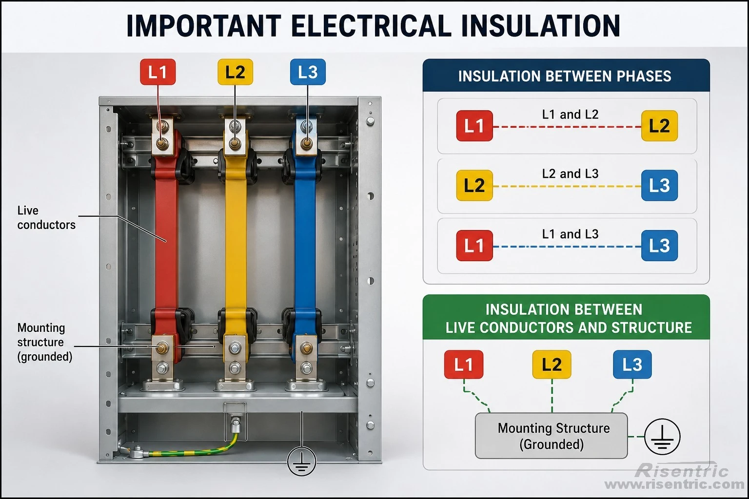
All outgoing terminals on the same phase are connected to one common conductive body. They are parallel take-off points at the same electrical potential, not independent circuits. The moulded walls physically separate the cable-entry positions, while the main electrical insulation is between L1, L2 and L3.
All outgoing terminals belonging to the same phase are electrically connected.
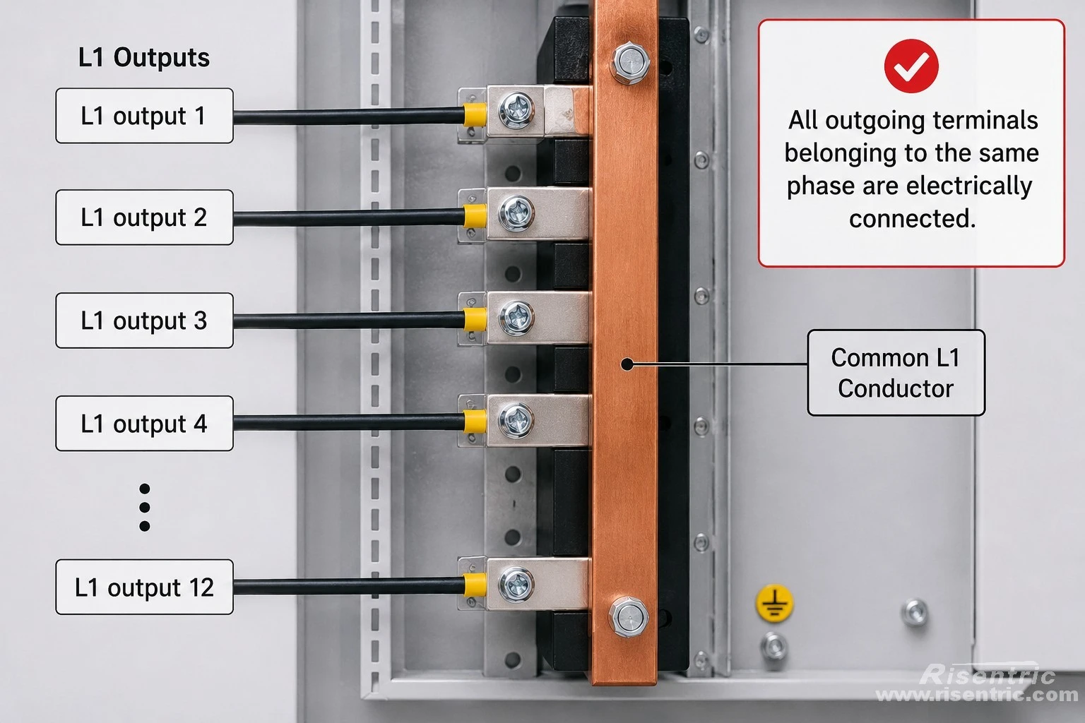
If phase L1 is energized, every L1 output terminal is energized.
The plastic walls between adjacent terminal openings provide physical separation, not electrical isolation.
These barriers help to:
- guide the conductors
- prevent loose cable strands from touching another terminal
- maintain spacing
- reduce accidental contact
- organize the wiring
The important electrical insulation is between:
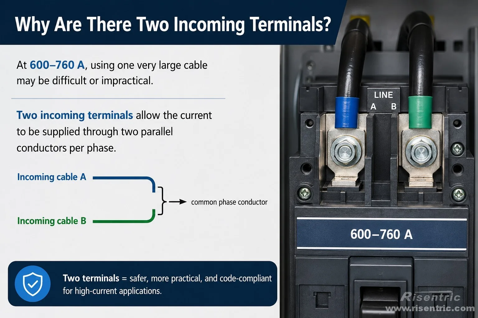
Why Are There Two Incoming Terminals?
At 600–760 A, using one very large cable may be difficult or impractical.
Two incoming terminals allow the current to be supplied through two parallel conductors per phase.
However, the two conductors must share the current properly.
They should normally have:
- the same conductor material
- the same cross-sectional area
- approximately the same length
- similar routing
- identical termination quality
If one cable has lower resistance, it may carry more current than the other and become hotter.
The two incoming terminals are electrically connected. They should not be used to connect two unrelated power sources.
Distribution Block and Safety
What Is a Good Current Margin?
For normal indoor applications, a practical design target is to operate the block at approximately 75–80% of its published current rating.
This is an engineering recommendation rather than a universal UL or IEC requirement.
For the Square D 9080LBA365212 with copper conductors:
| Rated voltage | 600 V AC/DC |
| Current with copper conductors | 760 A |
| Assumed continuous load current | 600 A |
600 A ÷ 760 A ≈ 79%
This means a 600 A load uses approximately 79% of the block’s published copper current rating.
The remaining nominal current margin is approximately:
760 A − 600 A = 160 A
or about 21%.
This makes the 760 A block a sensible choice for a 600 A copper application under normal conditions.
How Much Lower Is the Resistive Heating at 600 A?
Resistive heating increases approximately with the square of the current.
The relative resistive loss can be estimated as:
(600 ÷ 760)² ≈ 0.62
This means that, in theory, the resistive loss at 600 A is approximately 62% of the loss at 760 A, assuming:
- the electrical resistance remains unchanged
- the same cables are used
- the same cooling conditions apply
This does not mean the actual temperature rise will be exactly 62%.
The final temperature also depends on:
- ambient temperature
- cabinet ventilation
- terminal resistance
- heat from nearby breakers
- cable temperature
- panel IP rating
Recommended Loading Under Different Conditions
| Operating condition | Suggested maximum continuous loading |
|---|---|
| Normal indoor panel | 75–80% |
| Warm electrical room | 70–75% |
| Sealed IP54 or IP65 panel | 65–75% |
| Ambient temperature near 50°C | 60–70%, unless thermally verified |
| Significant harmonics | 60–70% |
| Uncertain future load growth | 60–70% |
| Continuous operation near 100% | Not preferred without verification |
The complete panel design should still be checked through temperature-rise calculation, comparison with a verified design or physical testing.
Does a Power Distribution Block Provide Protection?
No.
A standard distribution block does not detect or interrupt:
- overload current
- short-circuit current
- earth-fault current
- phase loss
- terminal overheating
It is a passive conductive component.
Protection must come from the surrounding breakers and fuses.
Three Levels of Protection Must Be Considered
1. Protection of the incoming feeder
The upstream breaker or fuse protects the incoming feeder and limits the current supplied to the distribution block.
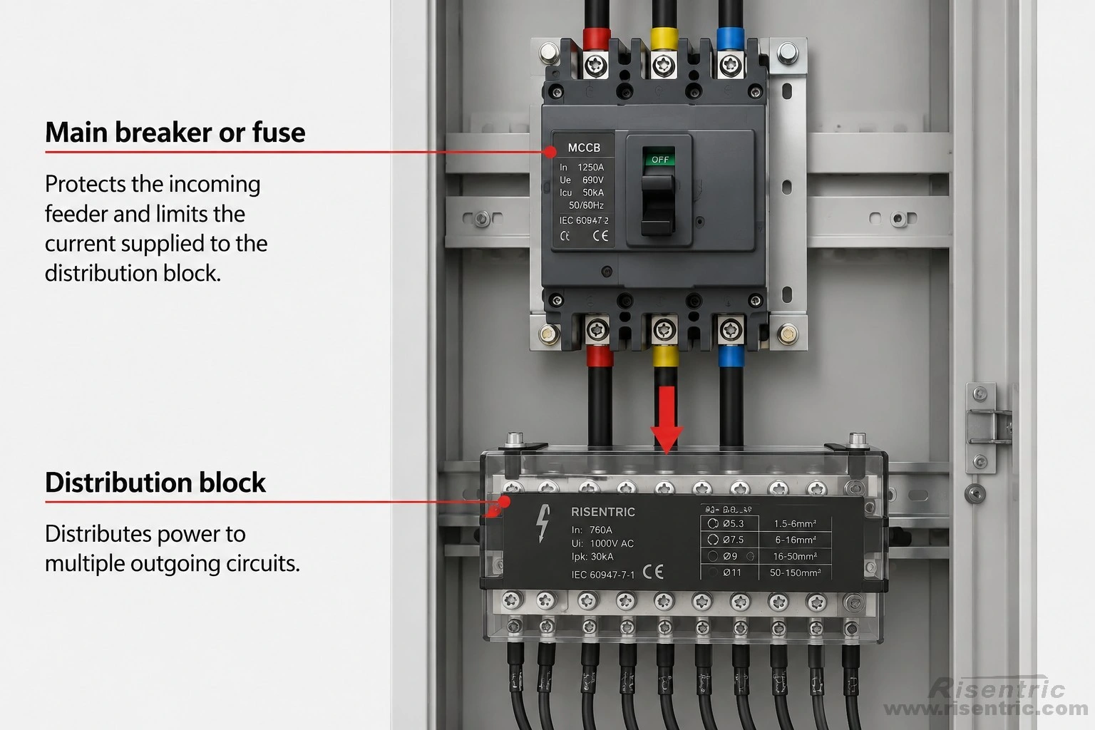
The upstream protective device must be coordinated with:
- incoming conductor ampacity
- distribution-block rating
- expected load current
- available short-circuit current
2. Protection of each outgoing conductor
A large upstream breaker cannot normally protect smaller outgoing cables against overload.
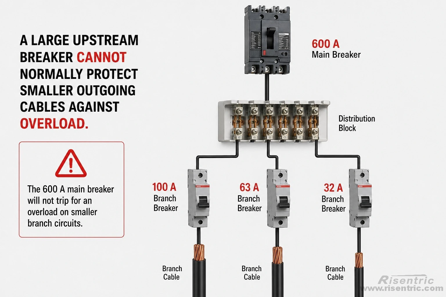
Each outgoing cable normally requires its own properly selected breaker or fuse.
This leads to one of the most important design principles:
The distribution block divides the current, but it does not divide the protection.
3. Short-circuit protection
Continuous-current rating and short-circuit rating are different.
The continuous-current rating tells us how much current the block can carry during normal operation.
The short-circuit current rating, or SCCR, tells us the fault-current level the block can withstand under specified protective-device conditions.
The distribution block does not interrupt the short circuit.
The upstream fuse or breaker interrupts it.
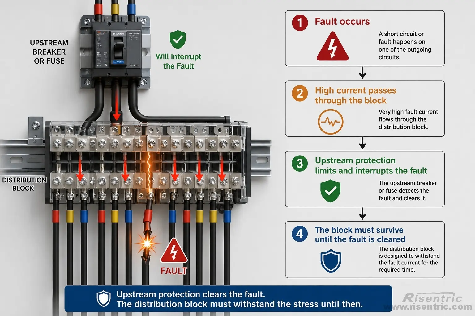
The permitted SCCR may depend on:
- upstream fuse type
- breaker type
- protective-device rating
- system voltage
- conductor size
- installation conditions
A published 100 kA SCCR should not be interpreted as unconditional compatibility with every breaker or fuse.
The exact manufacturer coordination conditions must be followed.
What Happens During a Short Circuit?
A short circuit creates two major stresses.
Thermal stress
High current produces rapid heating in:
- the conductive body
- cable interfaces
- terminal screws
- connected conductors
Electrodynamic stress
The magnetic fields around high-current conductors create strong mechanical forces.
These forces may:
- pull conductors from terminals
- deform the conductive body
- damage terminal threads
- crack the insulating base
- move one phase toward another
This is why short-circuit performance cannot be determined only from metal thickness.
Can Overheating Cause an Explosion?
The more common serious failure is:
- local overheating
- melted insulation
- smoke
- cabinet fire
However, overheating can develop into a much more severe electrical fault.
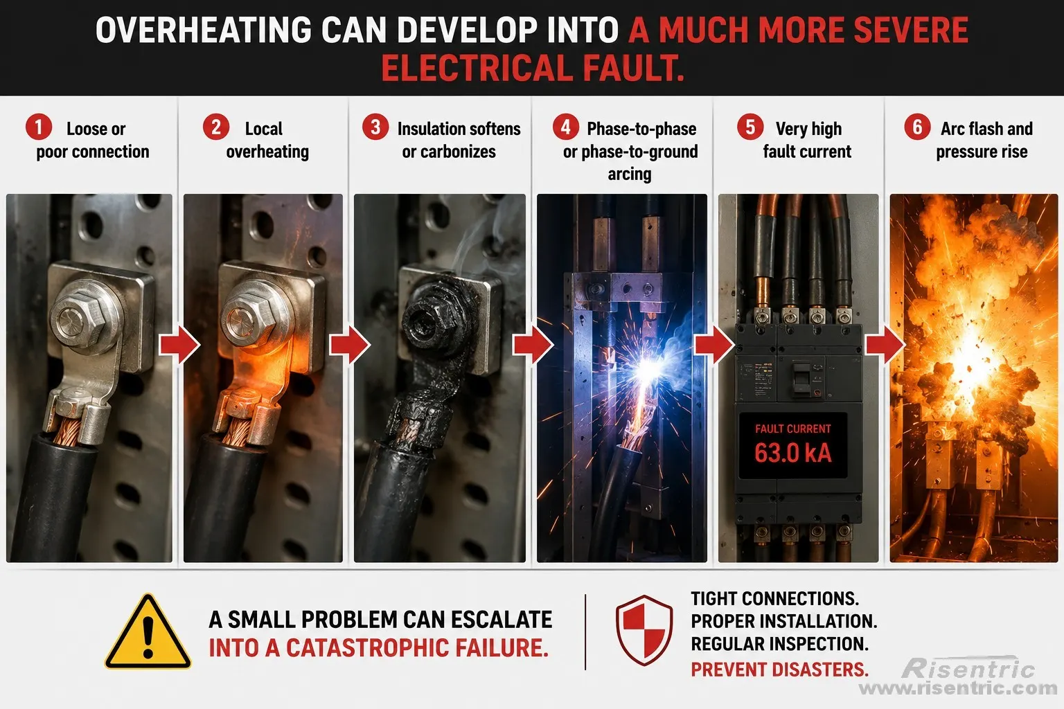
An electrical arc can rapidly heat and vaporize metal.
Inside a closed cabinet, this may produce:
- molten metal
- expanding hot gas
- pressure wave
- enclosure damage
- cabinet door movement
- fire
- serious injury
The block itself does not chemically explode.
The explosion-like event is an arc blast caused by the rapid release of electrical energy.
What Is the Typical Lifespan?
A power distribution block normally has no moving mechanism and no switching-cycle limit.
Under suitable conditions, it may remain in service for much of the life of the switchboard, potentially 20–30 years or longer.
However, its actual life depends mainly on:
- terminal torque
- continuous operating temperature
- thermal cycling
- vibration
- corrosion
- moisture
- contamination
- fault history
- conductor preparation
Replacement should normally be based on condition rather than calendar age.
Warning signs include:
- abnormal hot spots during thermal scanning
- brown or black discoloration
- melted or deformed insulation
- cracked insulating material
- corrosion
- damaged terminal threads
- burnt cable insulation
- evidence of arcing
- conductors that cannot be tightened securely
The block should also be inspected after a major downstream short circuit.
Looking for factory-tested 3-Phase switchgear & Panel boards for your project?
Conclusion
A power distribution block is a compact way to divide one high-current feeder into several smaller outgoing circuits. Its performance depends not only on the size of the conductive body, but also on terminal contact, clamping pressure, insulation, heat dissipation and short-circuit strength.
Using the Square D 9080LBA365212 as an example, two large incoming conductors can supply twelve outgoing connections per phase. The block itself does not provide circuit protection, so suitable upstream and branch protective devices are still required.
Its main advantage is that it provides a compact, standardized and documented alternative to a custom busbar arrangement.
FAQ
Does a power distribution block protect each branch circuit?
No. Each outgoing conductor normally requires a properly selected branch breaker or fuse.
Can a 760 A distribution block carry more than 760 A?
Do not assume so. The published rating should be treated as the maximum permitted rating under the manufacturer’s conditions.
Is the 9080LBA365212 suitable for a 600 A feeder?
With copper conductors, 600 A is approximately 79% of the 760 A rating, which is a reasonable design level under normal conditions.
With aluminium conductors, 600 A is approximately 97% of the 620 A rating, leaving very little practical margin.
Can a distribution block replace a busbar?
Yes, when local cable branching is required. A busbar is normally more suitable when power must be distributed across many breakers or cabinet sections.
Can terminal overheating cause an arc-flash event?
Yes. A poor connection may first cause local heating and insulation damage. If it develops into a phase-to-phase or phase-to-earth arc, a severe electrical fault may occur.


