
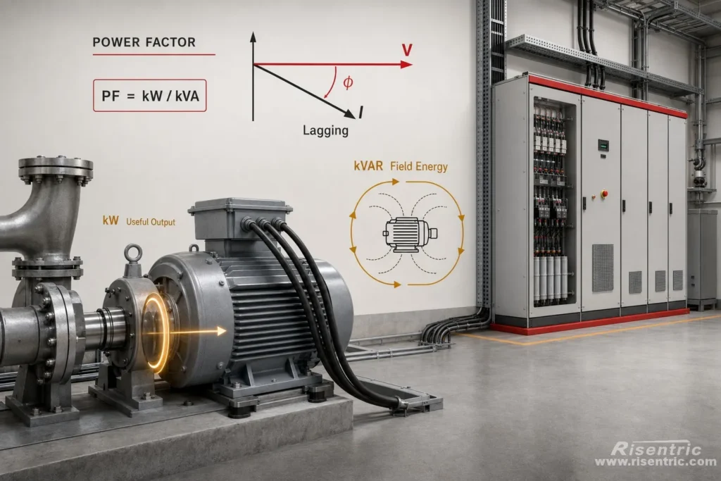
This is the starting point for understanding capacitor banks and APFC or PFI panels.
This article will dive into power factor, and expose the fact: the small power factor is not simply kind of loss. It’s actually caused by ‘Mismatch‘, either leading or lagging.
In future articles, we will discuss more aspects of APFC/PFI. Also, dive deeper into topics such as magnetic fields in other series.
A motor may be producing the required mechanical output, but the current flowing through the cable can still be much higher than expected.
Why?
Because in an AC system, current may have two responsibilities:
- Transferring energy that becomes mechanical work, heat, or light.
- Building and collapsing magnetic or electric fields inside the equipment.
Power factor tells us how much of the electrical capacity supplied to a load is being converted into active power.
kW, kVAR and kVA
To understand power factor, we need to separate three types of electrical power.
| Term | Name | Meaning |
|---|---|---|
| kW | Active power | Power converted into useful output, heat, light, motion, and equipment losses |
| kVAR | Reactive power | Power exchanged with magnetic or electric fields |
| kVA | Apparent power | Total electrical capacity carried by the system |
For a sinusoidal system:
kVA² = kW² + kVAR²
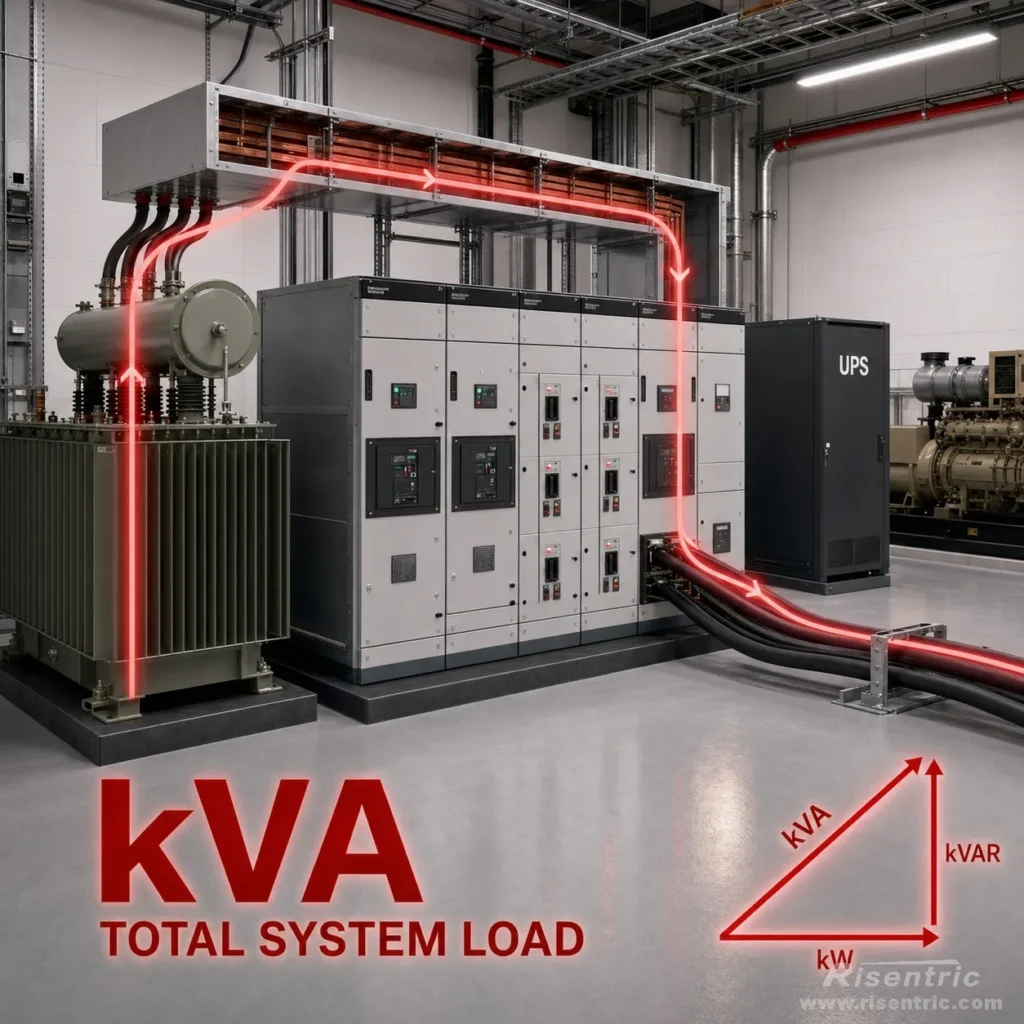
This relationship is often shown as a power triangle:
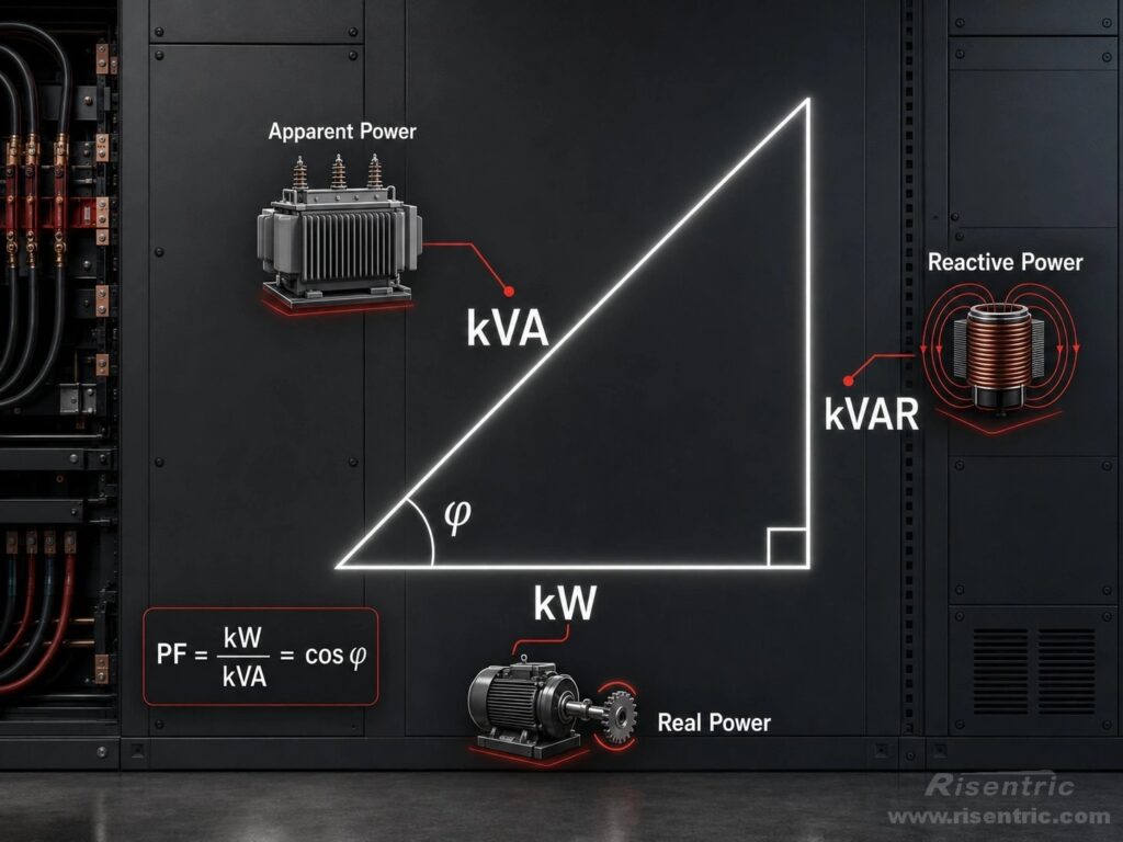
The greater the reactive-power component, the larger the kVA required to deliver the same kW.
What Is Power Factor?
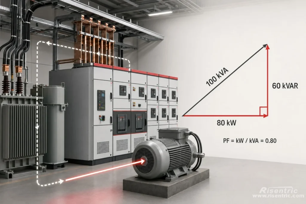
Power factor is the ratio between active power and apparent power:
Power Factor = Active Power ÷ Apparent Power
Or:
PF = kW ÷ kVA
The value normally ranges from 0 to 1.
A power factor of 1 means that all the apparent power supplied to the load is being converted into active power.
A power factor of 0.8 means that a system must supply 100 kVA to deliver 80 kW of active power.
In this case, the reactive power is 60 kVAR, because:
100² = 80² + 60²
In a sinusoidal system, the remaining component is 60 kVAR of reactive power. It represents energy moving back and forth between the source and the load rather than energy permanently consumed by the load. Nonlinear loads can also reduce power factor through current waveform distortion, which will be discussed later.
Active Power: kW
Active power is the part that produces a net transfer of energy.
For example, it can:
- Turn a motor shaft
- Heat an electric heater
- Produce light
- Operate electronic equipment
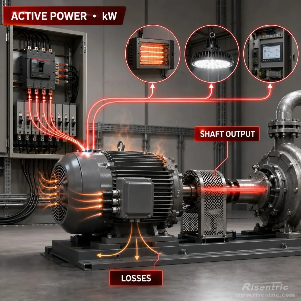
An electric motor also consumes some active power through copper losses, iron losses, friction, and ventilation. Therefore, not all active power becomes useful mechanical output, but it is still real energy consumed by the load.
Reactive Power: kVAR
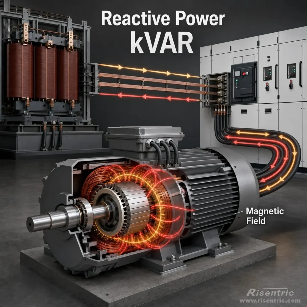
Motors, transformers, reactors, and other inductive devices need magnetic fields to operate.
During part of each AC cycle, energy is taken from the supply and stored in the magnetic field. When the field weakens, much of that energy returns toward the supply.
This exchange repeats continuously.
Reactive power is therefore not imaginary or unnecessary. A motor needs its magnetic field. The problem is that when the reactive current comes from the upstream grid, it must travel through the transformer, switchgear, busbars, cables, and circuit breakers.
These components must carry the current even though that part of the current does not create net mechanical output.
Apparent Power: kVA
Apparent power represents the total loading placed on the electrical system.
Transformers, generators, UPS systems, busbars, cables, and switchgear are commonly sized according to current or kVA because they must carry both active and reactive current.
Can Power Factor Reach 1?
Natural power factor of the load itself
A power factor of 1 is physically possible. An ideal resistive load has no reactive-power demand, so its active power and apparent power are equal.
An induction motor alone, however, normally cannot reach a power factor of 1 because it always requires magnetizing current to establish its rotating magnetic field.
After adding capacitor compensation
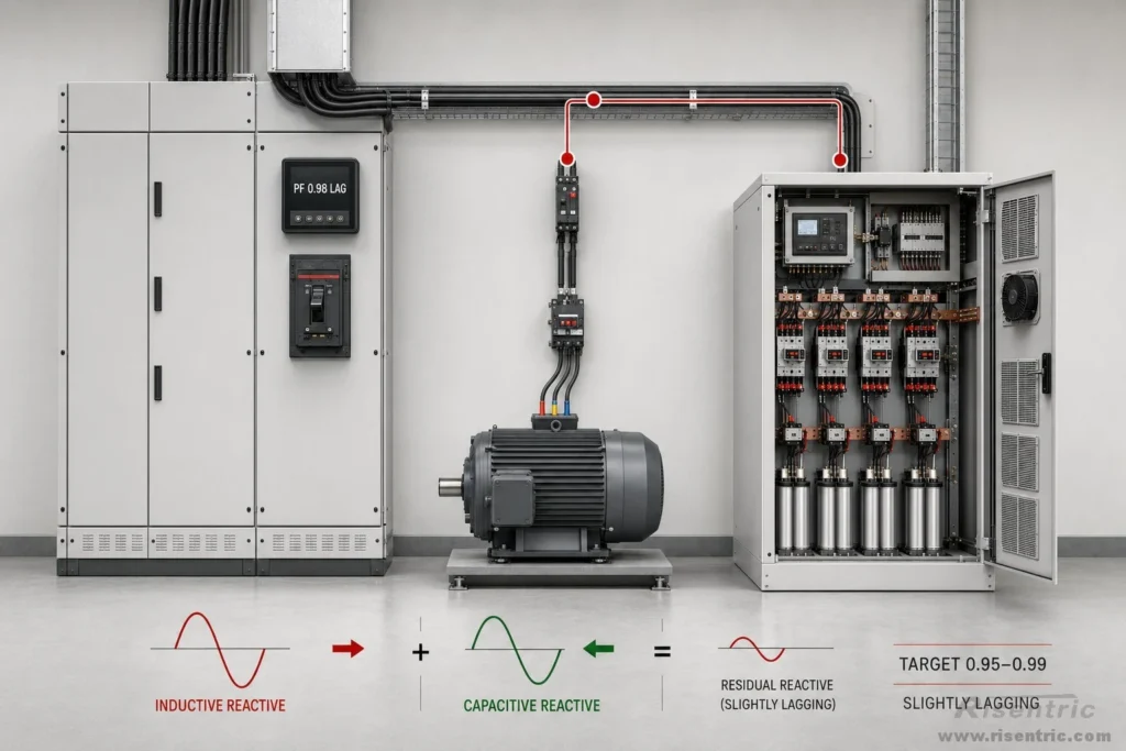
A capacitor bank can offset the motor’s inductive reactive current. At a particular load condition, the combined motor-and-capacitor system may therefore appear to have a power factor very close to 1 when measured from the upstream supply.
Maintaining exactly 1.00 is difficult in practice because industrial loads continuously change and capacitor banks switch in fixed steps. Harmonic distortion can also keep the true power factor below 1 even when voltage and fundamental current are closely aligned.
For this reason, an APFC system is normally designed to maintain a stable high power factor, often around 0.95 to 0.99, rather than continuously pursuing exactly 1.00. A small lagging margin also helps prevent overcompensation and leading power factor.
Power Factor, Phase Angle, and Leading or Lagging Direction
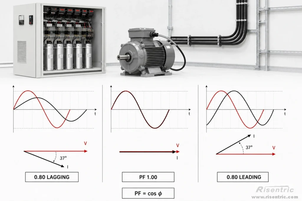
Power factor has both a magnitude and a direction.
The magnitude shows how far the current is shifted from the voltage. The direction shows whether the current is ahead of or behind the voltage.
For a sinusoidal AC system without significant harmonic distortion:
PF = cos φ
Here, φ is the phase angle between the voltage and current of the same phase.
For example:
- Current 37° behind voltage means 0.80 lagging
- Current 37° ahead of voltage means 0.80 leading
Both have the same power-factor magnitude because:
cos 37° ≈ 0.80
This is similar to −1 and +1. Both are one unit away from zero, but they point in opposite directions.
| Current relative to voltage | Power factor |
|---|---|
| 37° behind | 0.80 lagging |
| Aligned | 1.00 |
| 37° ahead | 0.80 leading |
Lagging Power Factor
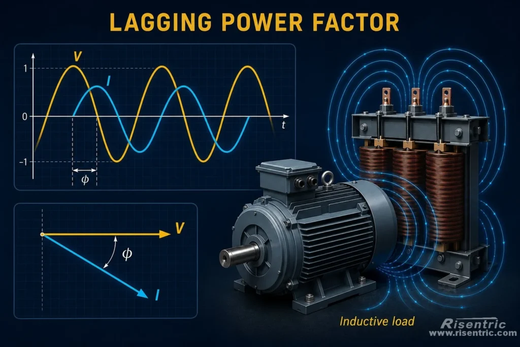
In an inductive load, current reaches the same point in its cycle later than voltage. The current therefore lags the voltage.
Common inductive loads include:
- Induction motors
- Transformers
- Reactors
- Solenoids
- Magnetic ballasts
These loads temporarily store energy in magnetic fields, causing the current waveform to shift behind the voltage waveform.
Leading Power Factor
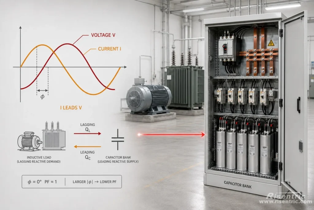
In a capacitive load, current reaches the same point in its cycle earlier than voltage. The current therefore leads the voltage.
Capacitor banks produce leading reactive current, which can offset part of the lagging reactive current drawn by motors and transformers.
A lagging power factor normally means the system is dominated by inductive loads.
A leading power factor normally means the system is dominated by capacitive loads or has been overcompensated by a capacitor bank.
When voltage and current are perfectly aligned:
φ = 0°
Therefore:
PF = 1
As the phase-angle magnitude increases, the power-factor magnitude decreases.
Do Not Confuse This Angle with the 120° Between Three Phases
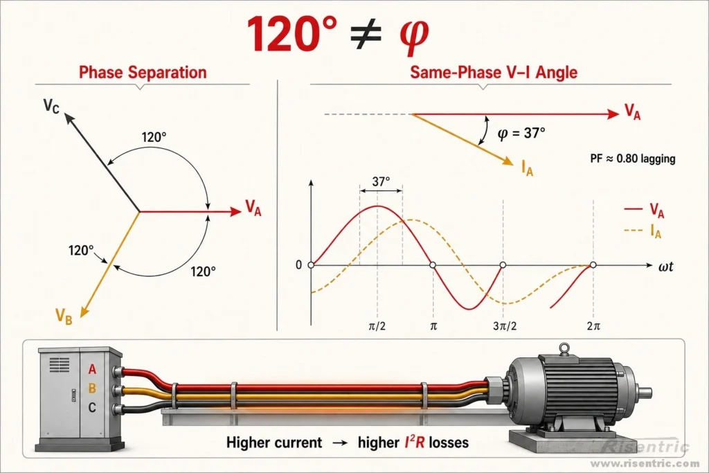
In a balanced three-phase system, the Phase A, Phase B, and Phase C voltages are separated from one another by 120°.
This 120° separation is a normal feature of a three-phase supply. It does not reduce the power factor.
Power factor is determined by comparing each phase voltage with its corresponding phase current:
- Phase A voltage with Phase A current
- Phase B voltage with Phase B current
- Phase C voltage with Phase C current
For a balanced resistive load, the three voltages are still 120° apart, but each phase current is aligned with its own voltage. The voltage–current angle is therefore 0°, and the power factor is 1.
For a balanced motor, the three currents may also remain 120° apart from one another, while each current lags its corresponding voltage by 37°.
In that case:
PF ≈ 0.80 lagging
The key point is:
The 120° angle describes the separation between the three phases. The power-factor angle φ describes the shift between voltage and current on the same phase.
In a motor, this phase shift is caused by the magnetizing current required to establish the magnetic field.
The phase shift does not directly represent lost energy. However, it means more total current is required to deliver the same active power. That higher current creates additional losses in cables, transformers, busbars, and switchgear.
Looking for industrial power distribution solutions for your project?
Why Is Low Power Factor a Problem?
More current
Low power factor means the electrical system must carry more current to deliver the same active power.
Consider a three-phase load that requires 100 kW at 400 V:
Current = kW × 1000 ÷ (√3 × Voltage × Power Factor)
| Power Factor | Active Power | Apparent Power | Approximate Current |
|---|---|---|---|
| 1.00 | 100 kW | 100 kVA | 144 A |
| 0.80 | 100 kW | 125 kVA | 180 A |
| 0.60 | 100 kW | 167 kVA | 241 A |
The load receives 100 kW in every case. However, at a power factor of 0.60, the electrical system must carry approximately 241 A instead of 144 A.
This additional current affects the entire upstream system.
Higher Current Causes More Losses
Cable and busbar losses are related to the square of the current:
Loss = I²R
This means losses increase much faster than current.
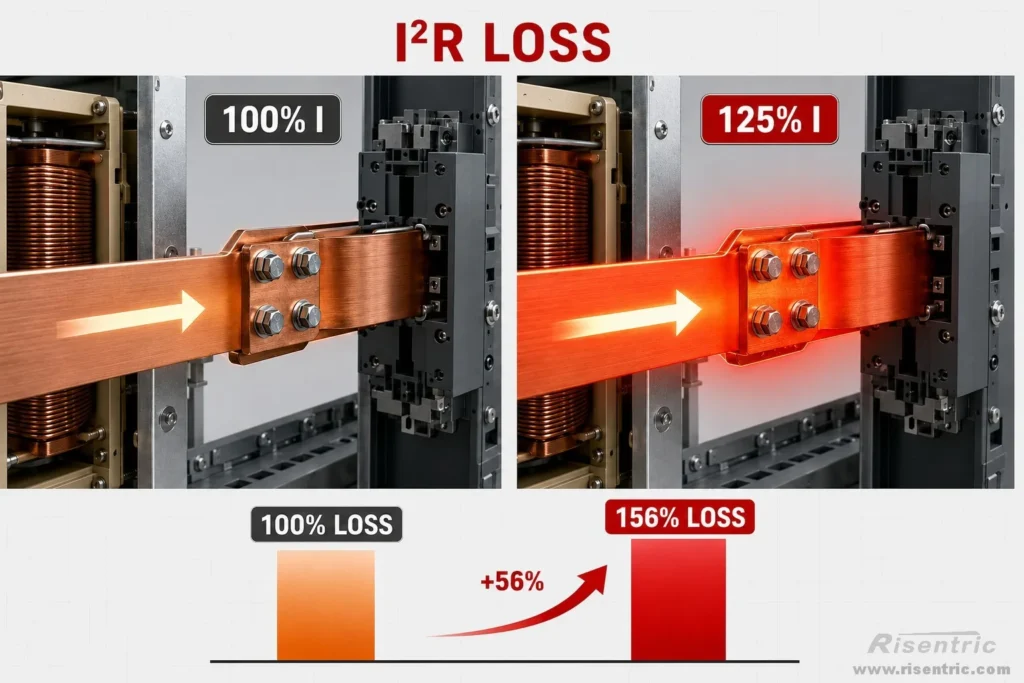
For example, when current increases by 25%, conductor losses increase by approximately 56%, assuming the resistance remains unchanged.
The additional losses appear mainly as heat in:
- Cables
- Busbars
- Transformer windings
- Generators
- Switchgear connections
Higher Current Uses More System Capacity
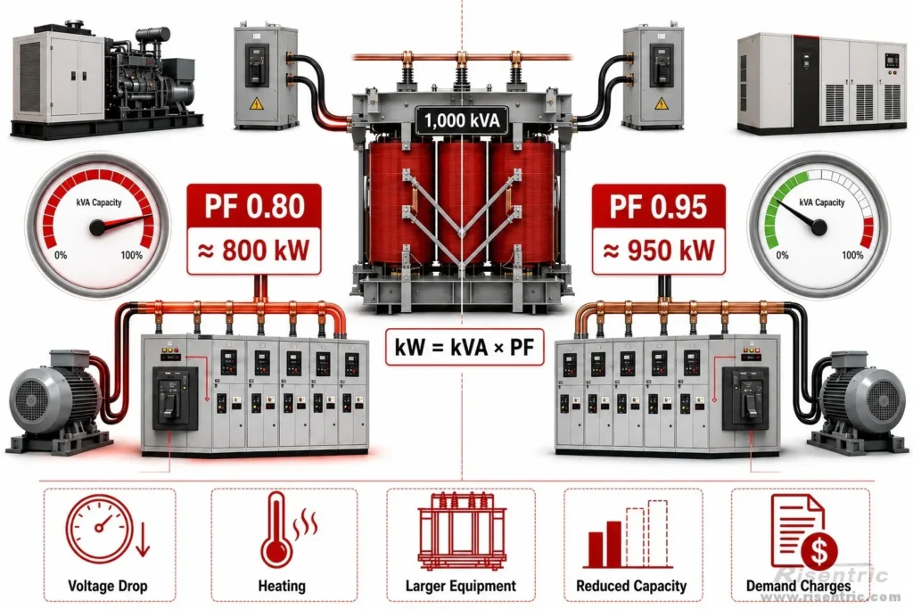
Transformers, generators, UPS systems, cables, circuit breakers, busbars, and switchgear must be selected according to the current or kVA they carry, not only according to the active power delivered to the load.
For example, a 1,000 kVA transformer supplying loads at a power factor of 0.80 can theoretically deliver only about 800 kW before reaching its full kVA rating.
At a power factor of 0.95, the same transformer can support approximately 950 kW under the same simplified conditions.
Low power factor therefore occupies system capacity that could otherwise be used to supply additional active loads.
Higher current can also cause:
- Greater voltage drop
- More heating
- Larger equipment requirements
- Reduced available transformer and generator capacity
- Reactive-energy or kVA-demand charges from the utility
Looking for industrial power distribution solutions for your project?
Improving Power Factor Saves Electricity
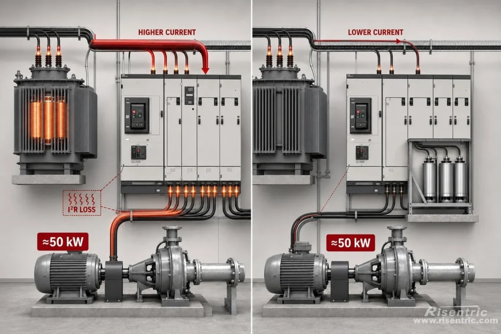
Improving power factor can save electricity because it reduces current and therefore reduces losses in cables, transformers, and other upstream equipment.
However, it does not reduce the power required by the machine itself.
For example, a pump that needs 50 kW will still need about 50 kW after power factor correction. The saving comes from reducing the extra power that was previously lost as heat in the electrical system.
Power Factor Can Also Be Affected by Harmonics
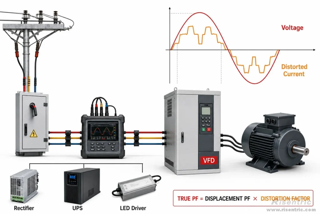
In a simple sinusoidal system, power factor mainly depends on the phase angle between voltage and current.
However, nonlinear equipment such as VFDs, rectifiers, UPS systems, and LED drivers can distort the current waveform. In these systems, power factor may be reduced not only by leading or lagging phase shift, but also by harmonic distortion.
A future article in this APFC/PFI series will explain harmonic distortion and its effect on power factor in more detail.
Conclusion
Power factor describes how much apparent power is required to deliver a certain amount of active power.
A low power factor does not necessarily mean the motor is producing less output. It means more current must flow through the electrical system to deliver the same active power.
For motors and transformers, reactive current is necessary to establish magnetic fields. But when that reactive current comes entirely from the upstream network, it occupies transformer, cable, busbar, and switchgear capacity and creates additional losses.
This leads to the basic purpose of power factor correction:
Supply part of the required reactive current locally so that less of it must travel through the upstream electrical system.
The next part of this series will explain how a capacitor performs this function and why it can reduce the reactive current drawn from the source.
FAQ
Is a power factor of 0.8 equal to 80% efficiency?
No. Power factor and efficiency are different measurements. A power factor of 0.8 means that active power is 80% of apparent power. It does not mean that 20% of the input energy is necessarily lost.
Does low power factor increase current?
Yes. For the same voltage and active power, a lower power factor requires higher current.
Why is motor power factor poor at light load?
A lightly loaded motor needs less active current to produce torque, but it still requires magnetizing current to maintain its magnetic field. Reactive current therefore becomes a larger proportion of the total current.
Is reactive power useless?
No. Reactive power supports the magnetic and electric fields required by motors, transformers, capacitors, and other AC equipment. The concern is the additional current it places on the distribution system.
Can a capacitor reduce motor current?
A capacitor connected for power factor correction usually reduces the current drawn from the upstream supply. It does not remove the motor’s need for magnetizing current. Instead, it supplies part of that current locally.
Can power factor be too high?
A high lagging power factor is normally desirable, but excessive capacitor compensation can create a leading power factor. This may cause voltage-control, switching, or resonance problems.
Does an APFC panel reduce kWh consumption?
It mainly reduces reactive-current flow, system losses, and possible utility penalties. It does not directly reduce the active energy required by the connected machinery.


