
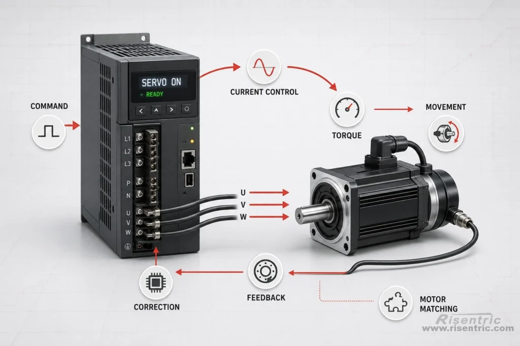
The idea of a servo system is simple.
- The motor must move.
- It must move in the way we want.
- It must move accurately.
To do this,
the servo drive must control the motor torque.
Torque comes from current, and the drive controls the current going into the motor.
But the drive also needs to know what the motor is actually doing. Without feedback, it cannot correct the movement or make the motor follow the command accurately. This is why feedback is needed. The encoder tells the drive the motor position and movement.
So the basic logic is:
Command → current → torque → movement → feedback → correction → Next command
The drive gives current to create torque. The motor moves. The encoder reports the actual position back to the drive. Then the drive adjusts the current again.
This article will talk about the essence of servo drive. Indeed, the existence of servo drive is mainly about 2 key concepts:
1. Control the current
2. Use feedback to know the motor position and control the current in the correct way.
Control the current
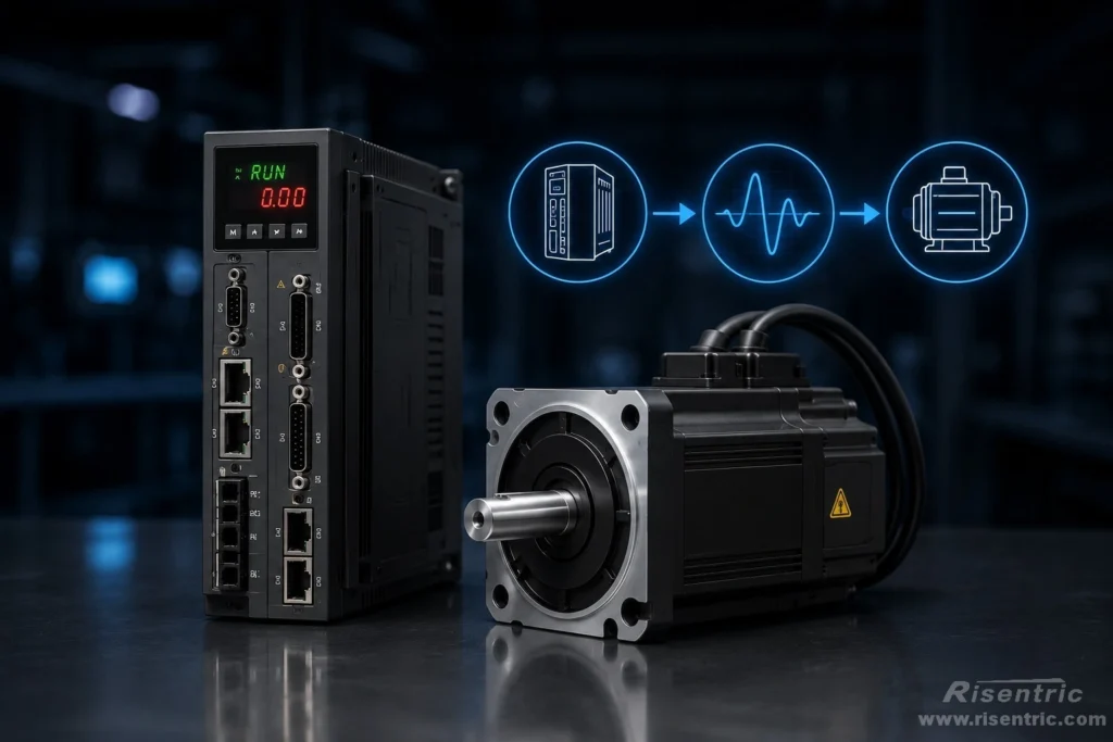
The first key point: A servo drive controls motor torque by controlling motor current.
So the drive must know the motor’s rated current, peak current, overload capacity, and thermal limit.
If the current is too low, the motor cannot produce enough torque.
If the current is too high, the motor may overheat or be damaged.
So current control is not an extra function. It is one of the core reasons the servo drive exists.
Power Conversion: The Basis of Current Control
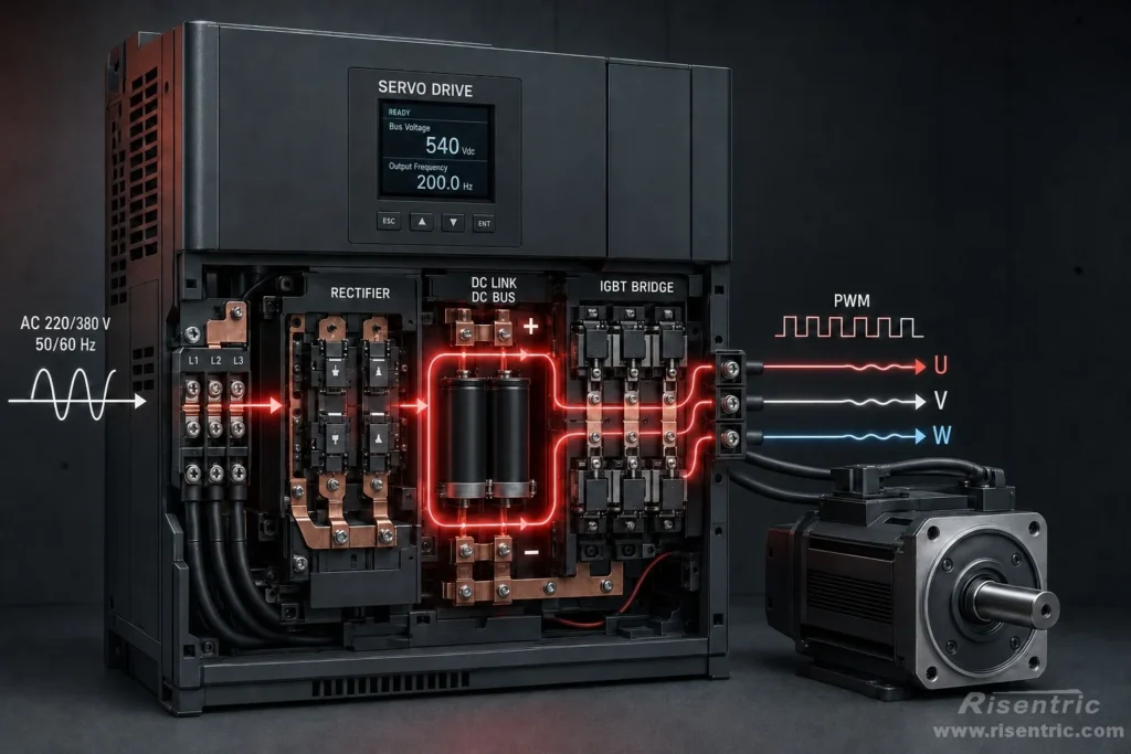
Because DC is just more flexible than AC.
A servo drive does not use the input AC power directly to run the motor.
The reason is simple: the input AC power is fixed, but the motor current needs to change all the time.
The power supply may be 220 V or 380 V, 50 Hz or 60 Hz. But the servo motor may need more current, less current, forward torque, reverse torque, acceleration, deceleration, or holding force at different moments.
So the servo drive first converts the input AC power into a DC bus.
Then it uses fast switching devices inside the drive to create controlled U/V/W output for the motor. This switching method is called PWM.
PWM can be understood like video frame rate.
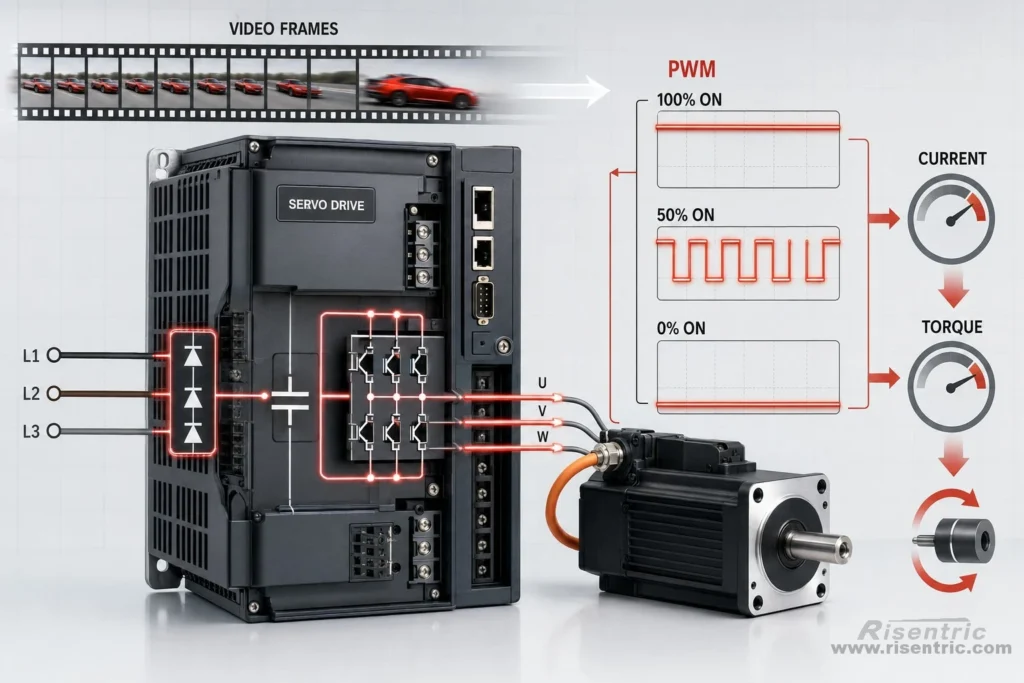
A video is made of many separate frames, but when the frames change fast enough, we see smooth motion.
PWM is similar. The servo drive switches the output on and off very quickly. Each pulse is not smooth by itself, but many fast pulses can create a controlled average effect.
If the switch is 100% ON, the output is full.
If the switch is 100% OFF, the output is zero.
If it is ON for only part of the time, the motor receives a controlled average effect.
E.g. If the switch is ON for 50% of the time, the motor receives about half of the effective output.
By changing this ON/OFF percentage, the servo drive changes the effective voltage applied to the motor. This changes the motor current, and the current creates torque.
Current feedback loop
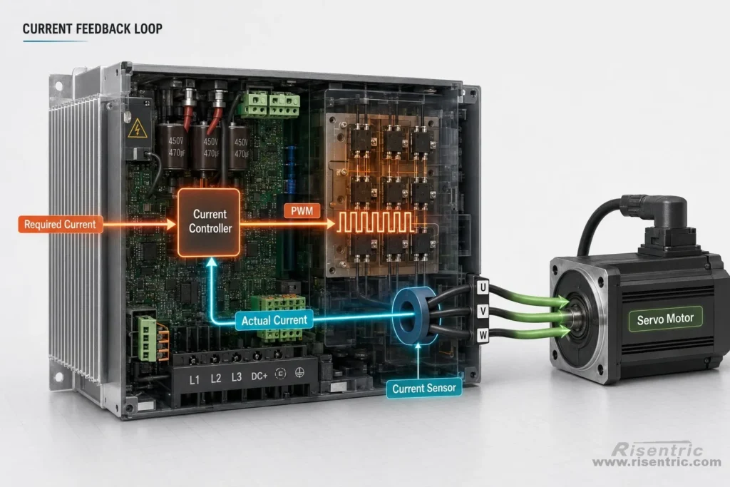
Before the feedback from the motor side, inside the servo drive, there is already a fast current feedback loop.
The drive measures the actual current flowing to the motor, compares it with the required current, and adjusts the PWM output continuously.
If the actual current is lower than required, the drive increases the PWM output to push more current into the motor.
If the actual current is higher than required, the drive reduces the PWM output.
This happens very quickly inside the servo drive and forms the foundation of torque control.
Its real purpose is to give the servo drive a controllable method to generate and regulate the exact motor current required.
The basic process is:
AC input → DC bus → PWM switching → controlled U/V/W output → motor current → motor torque
The DC bus works like an internal energy source. PWM works like a very fast control valve.
The voltage makes the motor current rise or fall. The drive measures the real motor current and adjusts the PWM again.
The drive converts fixed supply power into flexible motor current, and this current creates the torque that moves the motor.
Feedback from motor & better control the current
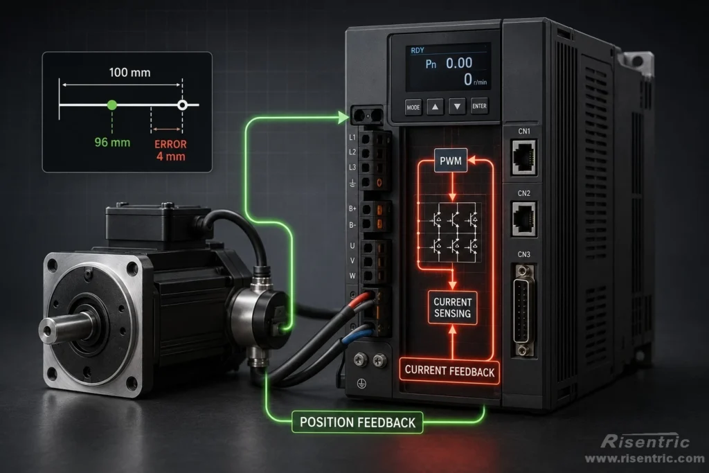
The second key point: position depends on feedback
The servo drive cannot control position accurately by guessing.
The encoder tells the drive the actual motor position, speed, and movement direction.
For example:
Command position: 100 mm
Actual position: 96 mm
Position error: 4 mm
After the drive knows this error, it can correct the motor movement.
A simple way to understand this is: Walking to a destination.
Encoder feedback tells you where you are.
Current feedback tells you how much force you are actually using for each step.
If you do not know where you are, you cannot reach the destination accurately.
If you do not control your force properly, your movement will be too weak, too strong, unstable, or inaccurate.
So the servo drive needs both.
The encoder feedback tells the drive the motor position.
The current feedback helps the drive control the motor torque.
Only when the drive knows where the motor is and can control the current correctly, the motor can move accurately.
Encoder and Decoder: Where Compatibility Matters
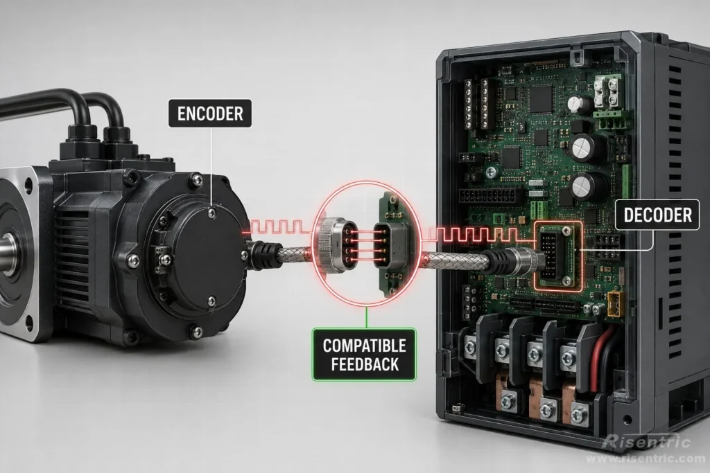
The encoder is on the servo motor.
Its job is to send feedback about the motor’s actual position, speed, and movement direction.
The decoder is inside the servo drive.
Its job is to read the encoder signal and turn it into useful position information for the drive.
In simple words:
Encoder = sender
Decoder = reader
The encoder sends the motor position information.
The decoder receives and understands that information.
This is where compatibility becomes critical.
If the encoder and decoder do not speak the same “language”, the servo drive cannot understand where the motor rotor is.
The drive must match the motor encoder in several ways:
- Encoder type
- Encoder protocol
- Encoder resolution
- Signal voltage
- Wiring pinout
- Absolute or incremental feedback
- Feedback direction
If the decoder cannot read the encoder signal correctly, the drive does not really know the motor position.
Then the motor may fail to Servo ON, report an encoder alarm, vibrate, jump, rotate incorrectly, or lose position.
This is why a servo motor cannot usually be connected to any random servo drive, even if the voltage and power look similar.
Different Feedback Methods
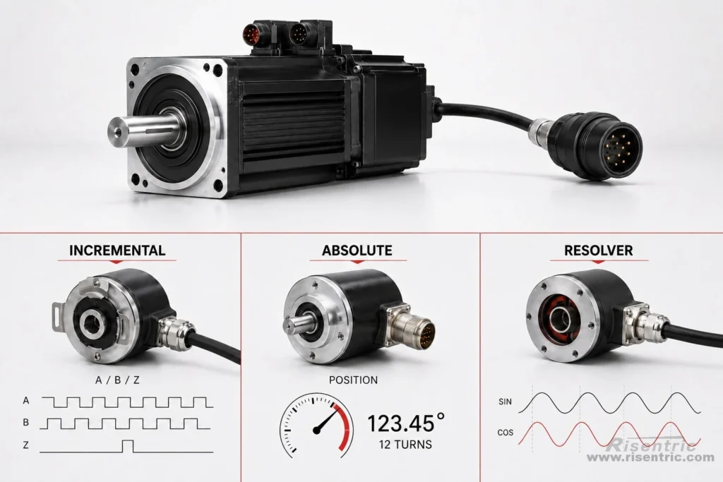
Servo motors do not all send feedback in the same way.
Some motors use an incremental encoder. It sends pulse signals such as A, B, and Z. The drive counts these pulses to know movement and position change.
Some motors use an absolute encoder. It can tell the drive the motor position directly, even after power is turned off and turned on again.
Some systems may use a resolver. It sends analog feedback signals, and the drive must convert them into position information.
Even if two servo motors have the same power rating, their feedback method may be completely different.
Feedback Also Helps the Drive Send Current to the Right Phase
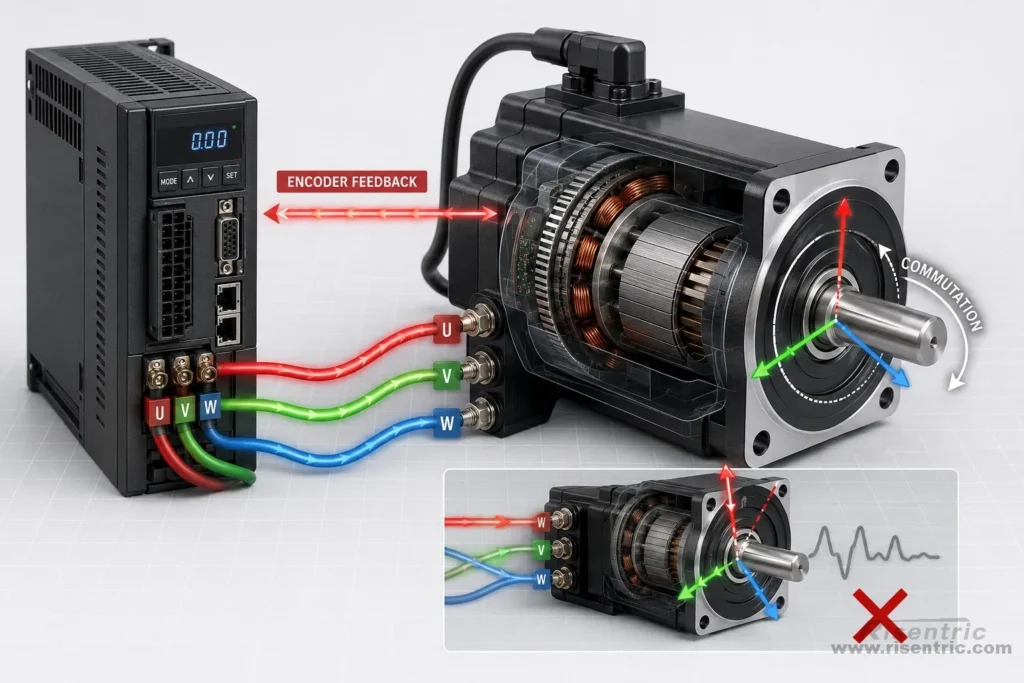
The servo drive does not only need to know how much current to output.
It also needs to know where to send the current.
A servo motor has U/V/W phases. The drive must energize these phases at the correct rotor angle. This is called commutation.
The encoder tells the drive where the rotor is. Then the drive can decide how to distribute current into U/V/W.
If the encoder direction, U/V/W phase sequence, or electrical angle does not match, the drive may send current at the wrong time.
The result can be vibration, jumping, alarm, wrong rotation, or failure to Servo ON.
This is why feedback compatibility is not only about position accuracy. It is also about whether the drive can create useful torque.
Common Troubleshooting
| Phenomenon | Reason |
|---|---|
| No movement, no heat, no vibration | Drive is probably not outputting effective current. Possible reasons: encoder mismatch, motor recognition failure, or motor parameter mismatch |
| Drive alarms immediately after Servo ON | Encoder type, protocol, pinout, motor model, or feedback recognition problem |
| Motor shakes or vibrates but does not rotate normally | Encoder direction, U/V/W phase sequence, or commutation angle mismatch |
| Motor jumps suddenly after Servo ON | Wrong encoder direction, wrong phase sequence, or wrong electrical angle |
| Motor moves weakly but cannot produce torque | Drive current too small, current limit too low, or wrong motor rated current setting |
| Motor can run unloaded but fails under load | Drive rated current or peak current is too small, or torque limit is too low |
| Motor overheats | Drive too large without proper current limit, wrong motor current parameter, or wrong tuning |
| Auto-tuning fails | Encoder mismatch, wrong motor parameters, or phase/feedback mismatch |
Where This Matters in Control Panel Design
In real projects, servo drives are usually not selected alone. They are part of a wider control system.
For example, in an MCC panel or automation control panel, the design may include motor feeders, protection devices, contactors, VFDs, PLC control, communication modules, and sometimes servo drive sections for precise motion control.
This is why servo drive selection should not only consider motor power. The designer also needs to check current rating, feedback type, encoder compatibility, control mode, wiring, protection, and communication requirements.
For larger motor control projects, these details should be confirmed together with the MCC or control panel design.
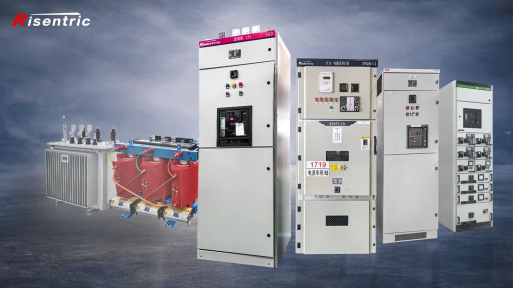
Looking for factory-tested 3-Phase switchgear & Panel boards for your project?
Conclusion
A servo drive is not just a power supply for a motor.
Its main job is to control motor current, because current creates torque. The drive must provide enough current for the required torque, but it must also keep the current within the motor’s safe range.
But current control alone is not enough.
The drive also needs feedback from the motor. The encoder tells the drive the actual position, speed, and movement direction. The decoder inside the drive must read and understand this feedback correctly.
This is why servo drive and servo motor matching is important.
The matching is not only about voltage and power. It is also about current capacity, encoder type, feedback protocol, wiring pinout, feedback direction, U/V/W phase sequence, electrical angle, and motor parameters.
In simple words, the servo drive must know three things:
- How much current to give.
- Where the motor is.
- How this motor reacts to current.
Only when these conditions match can the servo system move smoothly, accurately, and safely.
FAQ
1. Can any servo drive work with any servo motor?
No. A servo drive usually cannot work with any random servo motor. The drive must match the motor’s current rating, encoder type, feedback protocol, wiring, and motor parameters.
2. Why does encoder compatibility matter?
The encoder tells the servo drive the motor’s actual position, speed, and movement direction. If the drive cannot read this feedback correctly, it cannot control the motor accurately.
3. Is servo drive matching only about voltage and power?
No. Voltage and power are only part of the matching. Servo matching also depends on current capacity, encoder feedback, U/V/W phase sequence, electrical angle, and motor parameters.
4. Why does the servo drive convert AC to DC first?
The input AC power is fixed, but servo motor control needs flexible current control. The drive converts AC into a DC bus first, then uses PWM switching to create controlled U/V/W output for the motor.
5. What does PWM do in a servo drive?
PWM allows the servo drive to adjust the effective voltage applied to the motor. This controls the motor current, and motor current creates torque.
6. Why does the motor shake if the servo drive and motor do not match?
Shaking can happen when the drive sends current at the wrong phase or wrong rotor angle. This may be caused by encoder direction mismatch, U/V/W phase sequence mismatch, or incorrect commutation settings.
7. What happens if the drive current is too small?
If the drive current is too small, the motor may move weakly, fail under load, or fail to produce enough torque.


