
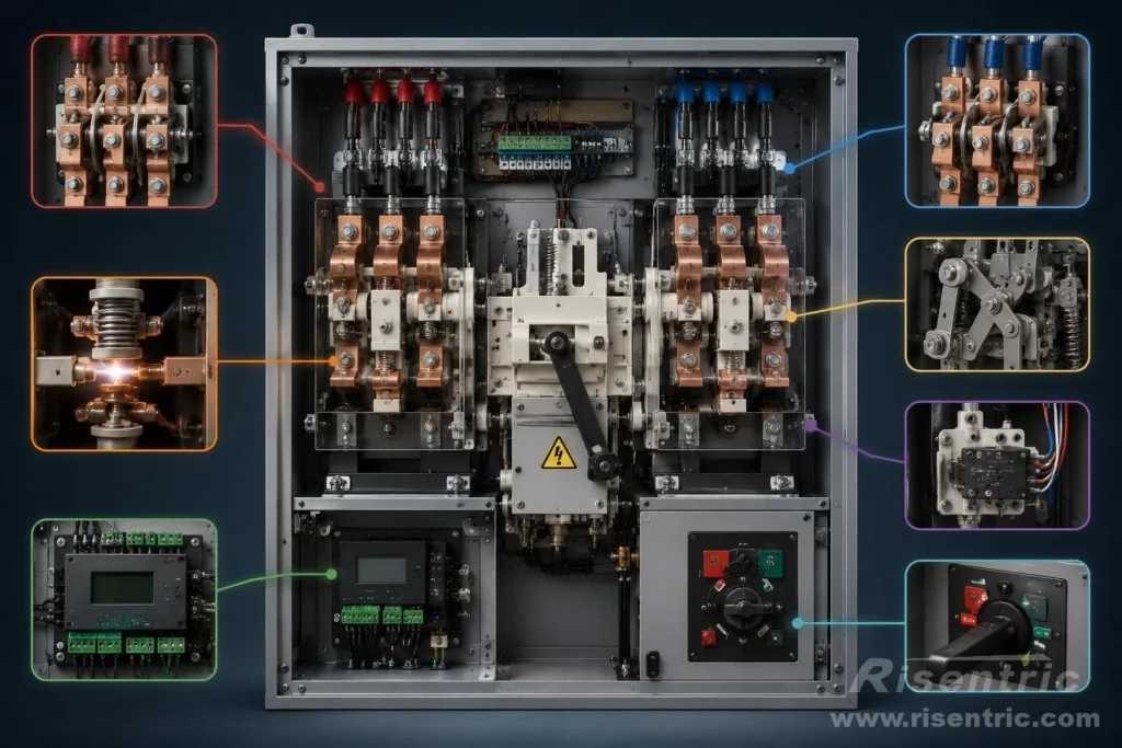
An ATS, or Automatic Transfer Switch, is often explained as a device that transfers load between a normal source and a standby source. This definition is correct, but it is incomplete.
To understand why an ATS can safely transfer electrical loads, we need to look inside the device.
This article focuses only on the internal structure and mechanical logic of ATS. For product selection, ratings, enclosure design, and quotation details, those topics should be discussed separately in an ATS specification guide or ATS panel product page.
Inside an ATS: The Internal Structure of an Automatic Transfer Switch
An Automatic Transfer Switch, or ATS, is not only a controller that chooses between two power sources. Inside the device, there is a complete electromechanical structure designed to carry current, move contacts, prevent unsafe source connection, and confirm the final switch position.
To understand ATS structure clearly, it is useful to divide it into three layers:
- Power Switching Core
- Operating Mechanism
- Safety and Interlocking Structure
This classification makes the structure easier to understand than listing every component separately.

| Layer | Main Parts | Function |
|---|---|---|
| Power Switching Core | Main contacts, moving contacts, busbars, neutral pole, arc control | Carries and transfers power |
| Operating Mechanism | Actuator, spring mechanism, manual handle, feedback contacts | Drives and confirms movement |
| Safety and Interlocking Structure | Mechanical interlock, electrical interlock, insulation, open/closed transition | Prevents unsafe operation |
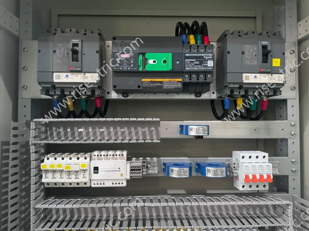
Looking for factory-tested ATS Switchgear & Panelboards for your project?
1. Power Switching Core
The power switching core is the part of the ATS that directly carries and transfers electrical power. It includes the main contacts, moving contact mechanism, terminals or busbars, neutral pole structure, and arc control structure.
This layer answers one basic question:
How does the ATS physically connect the load to Source I or Source II?
Main Contacts: The Current-Carrying Core

The main contacts are the current-carrying parts inside the ATS.
They connect the load to one of the available power sources:
| Source | Typical Meaning |
|---|---|
| Source I | Normal utility source, transformer, or main feeder |
| Source II | Generator, standby source, or secondary feeder |
When the ATS is in Source I position, the Source I contacts are closed and the Source II contacts are open. When the ATS transfers to Source II, the Source I contacts open and the Source II contacts close.
The main contacts must be designed to handle:
- rated operational current
- contact pressure
- temperature rise
- electrical wear
- mechanical wear
- short-circuit stress before upstream protection operates
From a structural point of view, the main contacts are the “muscle” of the ATS. If the contact pressure is weak or the contact surface is damaged, the ATS may suffer from overheating, voltage drop, unstable operation, or reduced service life.
Moving Contact Mechanism: How the ATS Changes Source

The moving contact mechanism physically changes the connection from one source to another.
Depending on the ATS design, this movement may be:
- rotary movement
- linear movement
- double-throw movement
- contactor-style movement
- breaker-based movement
Many low-voltage ATS devices use a three-position structure:
| Position | Meaning |
|---|---|
| I | Load connected to Source I |
| 0 / OFF | Load disconnected from both sources |
| II | Load connected to Source II |
This I-0-II structure is important because it supports the break-before-make principle. The ATS can pass through an OFF position before connecting to the other source, reducing the risk of accidental source paralleling.
In simple terms, the moving mechanism is the part that makes source transfer physically possible.
Terminals and Busbars: The Power Path

The terminals or busbars form the main power path of the ATS.
They connect:
- Source I incoming cable or busbar
- Source II incoming cable or busbar
- outgoing load cable or busbar
In small ATS devices, this may be a compact terminal structure. In larger ATS panels, the busbar arrangement becomes more important because it affects:
- current carrying capacity
- temperature rise
- cable termination space
- phase clearance
- creepage distance
- maintenance access
- short-circuit withstand performance
Although terminals and busbars may look like basic parts, they strongly affect installation quality and long-term reliability.
Neutral Pole Structure: 3-Pole and 4-Pole ATS

ATS devices may be built as 3-pole or 4-pole structures.
| Type | Structure |
|---|---|
| 3-pole ATS | Switches three phase conductors |
| 4-pole ATS | Switches three phase conductors plus neutral |
A 4-pole ATS includes a neutral pole that operates together with the phase poles. The neutral pole is not just an extra terminal. It affects neutral current path, grounding arrangement, generator system design, and source separation.
In this structure-focused article, the key point is simple:
The neutral pole is part of the ATS switching structure, not only part of external wiring.
Detailed selection between 3P and 4P should be discussed in an ATS specification guide, because it depends on earthing system, generator arrangement, project standards, and local electrical requirements.
Arc Control Structure: Managing the Switching Arc

When current-carrying contacts open, an electrical arc may occur.
The arc is affected by:
- load current
- system voltage
- power factor
- contact material
- contact separation speed
- circuit characteristics
- switching environment
The arc control structure helps manage this arc and protect the contact system.
Depending on the ATS design, arc control may include:
- arc chutes
- arc runners
- contact geometry
- fast contact separation
- insulation barriers
- air gap design
Although an ATS is usually not used as a fault-interrupting device like a circuit breaker, it still needs to handle normal switching stress safely. This is why ATS should not be understood as a simple mechanical selector. It is an engineered switching device.
2. Operating Mechanism
The operating mechanism is the part that drives, supports, and confirms the movement of the ATS.
This layer answers:
How does the ATS move, and how does the system know where it is?
Actuator: The Driving Force

The actuator provides the force needed to move the ATS from one position to another.
Common actuator types include:
| Actuator Type | Description |
|---|---|
| Motor operator | Uses a motor to drive the switching mechanism |
| Solenoid actuator | Uses electromagnetic force for movement |
| Magnetic actuator | Uses magnetic force to create fast movement |
| Manual actuator | Uses human force through a handle |
| Spring-operated mechanism | Stores and releases energy for switching |
The actuator does not carry the main load current directly. Its job is to operate the switching mechanism.
Different actuator designs may influence:
- switching speed
- mechanical endurance
- noise
- maintenance requirements
- manual operation method
- reliability under low control voltage
In many ATS designs, the actuator is separated from the main power path. This allows the control system to operate the switch while the main contacts remain mechanically robust.
Spring or Energy Storage Mechanism
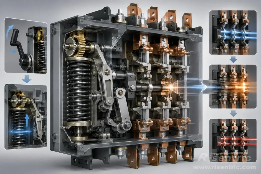
Some ATS designs use a spring or stored-energy mechanism.
The purpose is to make switching action more stable and repeatable.
Instead of relying only on slow motor movement, the motor or manual handle may first charge a spring. When the transfer command is given, the stored energy is released to complete the switching action more decisively.
This structure can improve:
- contact closing consistency
- contact opening force
- switching repeatability
- reduced arcing time
- mechanical stability
From an engineering view, stored-energy design separates the energy preparation stage from the actual switching stage.
That matters because good switching is not only about movement. It is about moving the contacts with enough force, speed, and repeatability.
Manual Operation Handle: Emergency and Maintenance Control

Most ATS devices provide a way for manual operation.
Manual operation may be used during:
- commissioning
- maintenance
- controller failure
- emergency operation
- testing
- manual source selection
The manual operation handle is usually mechanically connected to the switching mechanism. It allows an operator to transfer or isolate the ATS even when automatic control is not available.
A good manual operation structure should be:
- safe
- clearly indicated
- mechanically reliable
- protected from accidental operation
- compatible with maintenance or lockout procedures where required
Manual operation is important because ATS equipment must remain serviceable in real electrical installations, not only under ideal automatic conditions.
Position Feedback Contacts: Knowing the Real Switch Position

An ATS must know its own mechanical position.
Position feedback contacts are used to confirm whether the ATS is in:
- Source I position
- OFF position
- Source II position
These feedback signals may be sent to:
- ATS controller
- indicator lights
- generator controller
- alarm circuit
- building management system
- remote monitoring system
Position feedback is important because a command is not the same as a successful operation.
For example, the controller may command the ATS to transfer from Source I to Source II. But if the mechanism jams or the switch does not reach the final position, the controller must detect that condition.
In simple terms:
Position feedback closes the loop between mechanical movement and control logic.
3. Safety and Interlocking Structure
The safety and interlocking structure prevents unsafe operation.
This layer answers:
How does the ATS prevent two sources from being connected incorrectly?
Mechanical Interlock: Physical Safety

The mechanical interlock is one of the most important safety structures inside an ATS.
Its purpose is simple:
Source I and Source II must not be connected together accidentally.
In most ATS systems, the two sources are independent, such as:
- utility and generator
- two different transformers
- two utility feeders
- utility and UPS output
If two unsynchronized sources are connected together, the result may be severe fault current, equipment damage, generator instability, or safety hazards.
Mechanical interlocking physically prevents both source paths from closing at the same time. Even if a control error occurs, the mechanical structure helps block an unsafe physical position.
So mechanical interlock is the last physical safety barrier against source collision.
Electrical Interlock: Control-Circuit Safety

Electrical interlock prevents unsafe control commands.
In a normal open-transition ATS, the control system should not allow Source II to close while Source I is still closed. It should also not allow Source I to close while Source II is still closed.
Electrical interlocking may be achieved through:
- auxiliary contacts
- control relays
- controller logic
- limit switches
- position feedback circuits
- source availability signals
The basic logic is:
| Condition | Control Result |
|---|---|
| Source I is confirmed closed | Source II closing command is blocked |
| Source I is confirmed open | Source II closing command can be allowed |
| Source II is confirmed closed | Source I closing command is blocked |
| Source II is confirmed open | Source I closing command can be allowed |
So electrical interlock is essentially a logic safety system. It uses multiple condition checks to make sure only one source can close.
A simple expression would be:
Allow Source II Close =
Source I is confirmed open
AND Source II is available
AND no fault alarm
AND transfer command is valid
The difference between electrical and mechanical interlock is:
| Interlock Type | Function |
|---|---|
| Electrical interlock | Prevents unsafe commands |
| Mechanical interlock | Prevents unsafe physical closure |
Together, they create two layers of safety.
Insulation Barriers and Phase Separation
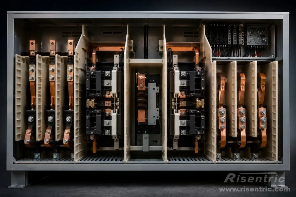
Inside an ATS, insulation barriers help separate live parts.
They may be used between:
- phases
- source terminals
- incoming and outgoing sections
- power parts and control parts
- arc zones and nearby components
The purpose is to reduce the risk of:
- accidental flashover
- phase-to-phase fault
- source-to-source fault
- contact between live conductive parts
This is especially important because an ATS contains multiple power paths inside one device. It must keep Source I, Source II, and the load path properly separated.
Good insulation design is not visible from outside, but it is essential for safe operation.
Open-Transition Structure: Break-Before-Make
Most ATS systems use an open-transition structure.
This means:
The first source opens before the second source closes.
The typical mechanical sequence is:
Source I contacts open
→ ATS passes through OFF or neutral position
→ Source II contacts close
This is also called break-before-make transfer.
The purpose is to prevent two sources from being connected together.
Open-transition structure may be achieved through:
- I-0-II mechanism
- mechanical interlock
- cam mechanism
- contact travel design
- position locking
Open transition is widely used because it is simple, safe, and suitable for many generator backup systems.
However, it usually creates a short power interruption during transfer. That timing topic should be discussed in a separate article about ATS reaction time, not in this structure article.
Closed-Transition Structure: Controlled Source Overlap
Some ATS systems are designed for closed transition.
Closed transition means:
The second source closes before the first source opens.
The typical sequence is:
Source II closes
→ Source I and Source II overlap briefly
→ Source I opens
This is also called make-before-break transfer.
The purpose is to reduce or nearly eliminate load interruption during source transfer. However, it is only safe when the two sources are acceptable and synchronized.
Closed transition requires:
- source synchronization
- voltage matching
- frequency matching
- phase angle checking
- protection coordination
- strict timing and feedback
So closed transition is not simply a faster mechanical switch. It is a controlled overlap structure that requires both mechanical capability and advanced control logic.
For most ATS applications, open transition is more common. Closed transition is mainly used where the system design allows temporary paralleling and where load interruption must be minimized.
Looking for factory-tested ATS Switchgear & Panelboards for your project?
Structural Comparison: Common ATS Mechanism Types
Different ATS designs use different internal structures.
| ATS Structure Type | Basic Principle | Common Characteristic |
|---|---|---|
| Contactor-type ATS | Uses mechanically/electrically interlocked contactors | Fast, compact, common in smaller systems |
| Motorized changeover switch ATS | Uses a motor-driven changeover mechanism | Clear I-0-II positions, strong isolation |
| Circuit-breaker-type ATS | Uses breakers as switching devices | Can integrate protection and switching |
| Static transfer switch | Uses semiconductor devices | Very fast, usually for sensitive loads |
This article focuses mainly on electromechanical ATS structures. Static transfer switches are structurally different because they rely on power electronics instead of mechanical contact movement.
Why ATS Structure Is Different from a Normal Switch
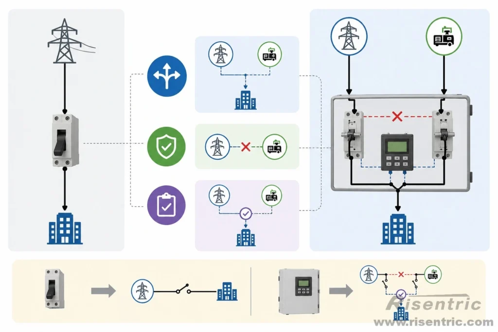
A normal switch usually connects or disconnects one source.
An ATS must manage at least two sources and one load.
This creates three special structural requirements:
- 1. Source Selection
The ATS must select which source supplies the load. - 2. Source Separation
The ATS must prevent unsafe connection between two sources. - 3. Transfer Confirmation
The ATS must confirm that the load has been transferred to the correct source.
Because of these requirements, ATS is more complex than a normal disconnect switch, isolator, or simple changeover switch.
Common Structural Problems in Poor ATS Design
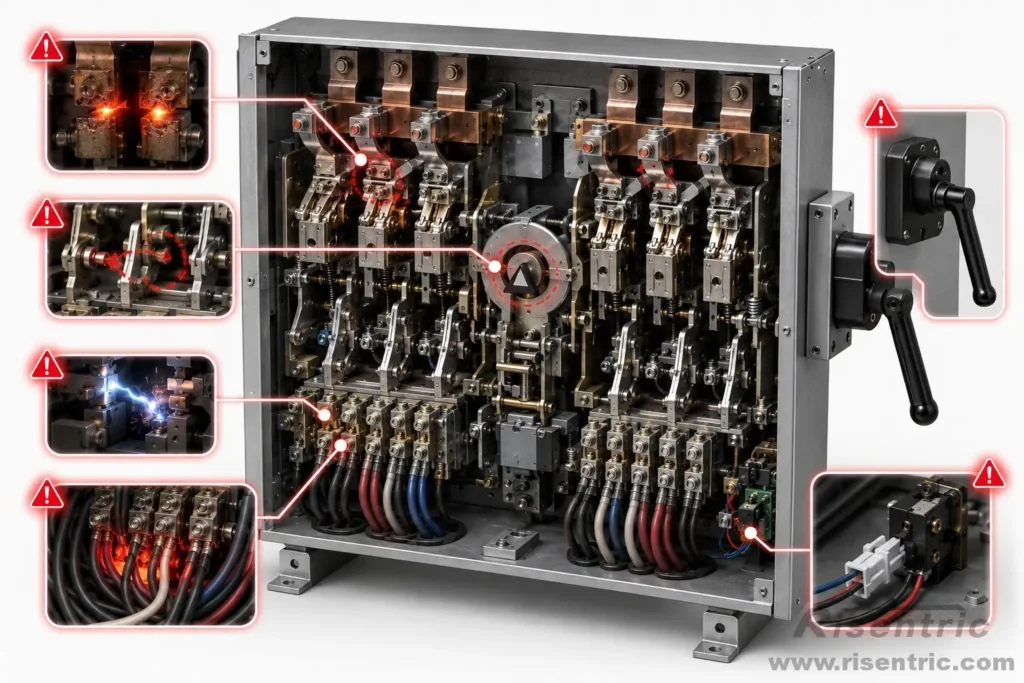
- 1. Weak Contact Pressure
Weak contact pressure may cause overheating, voltage drop, or contact wear. - 2. Poor Interlocking
Poor interlocking may create unsafe source paralleling risk. - 3. Unclear Position Indication
If operators cannot clearly see whether the ATS is in Source I, OFF, or Source II, operation becomes risky. - 4. Insufficient Terminal Space
Poor terminal arrangement may make installation difficult and increase heat concentration. - 5. Weak Manual Operation Design
Manual operation should be safe and intuitive, especially during emergency conditions. - 6. Poor Arc Management
Poor arc control may shorten contact life and reduce switching reliability. - 7. No Reliable Feedback
Without position feedback, the controller may not know whether the mechanical transfer actually succeeded.
Academic Summary: ATS as a Structured Electromechanical System
At the structural level, an ATS can be understood as an electromechanical system with three layers.
| Layer | Function |
|---|---|
| Power layer | Contacts, terminals, busbars, insulation, arc control |
| Mechanical layer | Actuator, linkage, spring, interlock, manual handle |
| Control interface layer | Auxiliary contacts, position feedback, controller interface |
The power layer carries and transfers current.
The mechanical layer creates safe and repeatable movement.
The control interface layer connects physical switch status with automatic control logic.
This layered structure explains why ATS reliability depends on more than the controller. Even the best controller cannot compensate for weak contacts, poor interlocking, insufficient insulation, or unreliable feedback.
In short:
The structure of an ATS is designed around one core engineering principle: transferring a load between two sources while preventing unsafe source connection.
Conclusion: To Understand ATS, Look at the Structure
The ATS is often described by its function, but its real engineering value lies in its structure.
Inside an ATS, the main contacts carry current, the actuator drives movement, the interlock prevents dangerous source connection, the arc control structure manages switching stress, and the feedback contacts confirm the final position.
This makes ATS more than an automatic switch. It is a structured electromechanical device designed for safe, repeatable, and controlled source transfer.
For users who want to understand ATS deeply, the internal structure is the best starting point.
FAQ
What is inside an ATS?
An ATS usually contains main contacts, moving contact mechanisms, mechanical interlock, electrical interlock, actuator, position feedback contacts, manual operating handle, terminals or busbars, and arc control structures.
What is the most important mechanical part of an ATS?
The mechanical interlock is one of the most important safety parts because it prevents the normal source and standby source from being connected together accidentally.
Why does an ATS have an OFF position?
Many ATS designs use an I-0-II structure. The OFF position helps ensure break-before-make transfer, meaning the load is disconnected from one source before connecting to another.
Is an ATS the same as a normal switch?
No. A normal switch usually controls one source. An ATS manages two sources and one load, so it requires interlocking, position feedback, transfer logic, and source separation.
What is the function of main contacts in ATS?
Main contacts carry the load current and connect the load to either the normal source or the standby source.
Why does ATS need arc control?
When current-carrying contacts open, an electrical arc may occur. Arc control structures help manage this arc and protect the contacts and insulation system.
What is mechanical interlock in ATS?
Mechanical interlock is a physical safety structure that prevents both source paths from being closed at the same time.
Does ATS always use a motor?
No. ATS may use motor operators, solenoids, magnetic actuators, spring mechanisms, or other operating systems depending on the design.


