
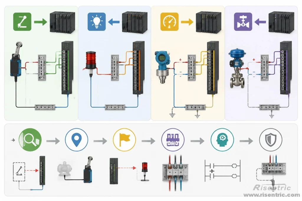
A PLC wiring diagram is basically a map of how field devices connect to the PLC, and how the PLC sends commands back to equipment.
The reading logic is simple:
Find the signal. Follow the wire. Identify the terminal. Understand the function.
The basic signal path is:
field device → PLC input → PLC program → PLC output → field device action
This article explains how to read a PLC wiring diagram from a practical control panel perspective.
For a direct live example, please refer to this.
PLC Wiring Diagram vs Power SLD
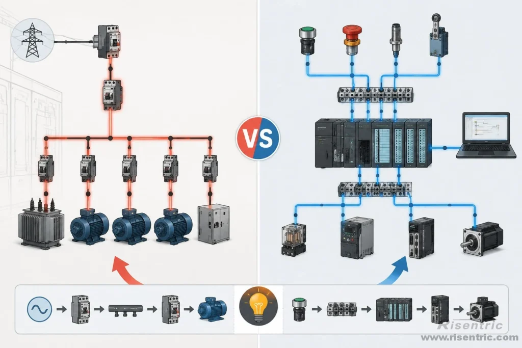
A PLC wiring diagram and a power SLD are not completely different in reading method.
Both drawings show connections. You still need to trace from one point to another and understand what each component does.
The difference is mainly the type of circuit.
In a power SLD, you usually trace the power path:
incoming supply → breaker → busbar → feeder → motor or load
In a PLC wiring diagram, you usually trace the control signal path:
field device → terminal block → PLC input
or:
PLC output → relay / VFD / servo drive → field device action
| Drawing Type | What You Trace | Common Components | Main Question |
|---|---|---|---|
| Power SLD | Power path | Breakers, busbars, transformers, feeders, motors | Where does the power go? |
| PLC wiring diagram | Control signal path | PLC terminals, relays, sensors, VFD terminals, terminal blocks | What signal enters or leaves the PLC? |
In both cases, the basic skill is the same:
follow the connection, identify the component, and understand the function.
Basic Reading Method Before the Live Example
Click here to jump to the live examples.
Before reading a real PLC wiring diagram, use three basic steps.
1. Find the PLC Module
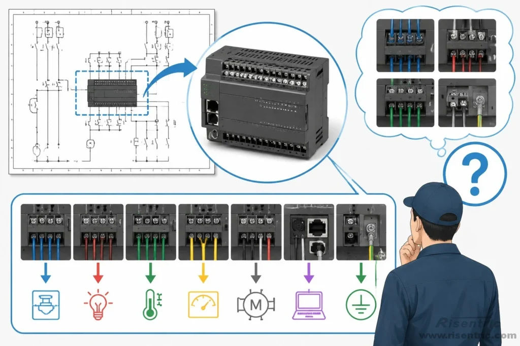
First, find the PLC or PLC I/O module on the drawing.
The PLC may be marked as:
- CPU
- PLC
- controller
- digital input/output module
- analog input/output module
- expansion I/O module
- communication module
The PLC module is usually drawn as a rectangle with many terminals.
Common terminal labels include:
| Terminal Label | Meaning |
|---|---|
| X / DI | Digital input |
| Y / DO | Digital output |
| AI | Analog input |
| AO | Analog output |
| 24V | Control power positive |
| 0V | Control power common |
| COM | Common terminal |
| RS485 A/B | Communication terminal |
2. Do Not Read Only the Terminal Number
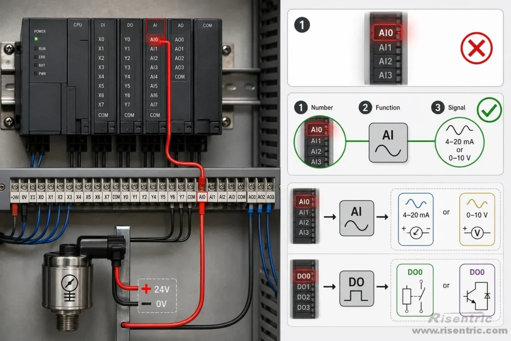
A terminal number only tells you where the wire is connected.
It does not fully explain the circuit.
For example, X6 only tells you the signal enters PLC input X6.
But if the drawing says:
X6 = Power Healthy
Now the signal has meaning.
The reading path may be:
24V → KM2 auxiliary contact → PLC input X6
If the KM2 contact closes, 24V reaches X6, and the PLC reads X6 as ON.
So the PLC program can understand:
X6 = ON → Power Healthy condition is true
The key point is:
Do not stop at the terminal number. Find the signal name and the device behind it.
3. Follow Wire Numbers and Cross-References
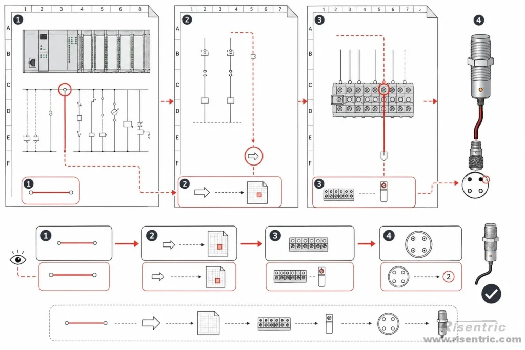
One PLC signal may not stay on one page.
It may go through:
- wire number
- cross-reference
- relay contact
- terminal block
- connector
- another drawing sheet
- field device
So do not read the drawing only from left to right.
Read it by tracing the signal path.
For a PLC input, the path may be:
field device → connector → terminal block → PLC input
For a PLC output, the path may be:
PLC output → relay / drive → connector → field device
The rule is simple:
Find the signal, follow the wire, identify the terminal, understand the function.
Live Example: Reading a Real PLC Wiring Drawing
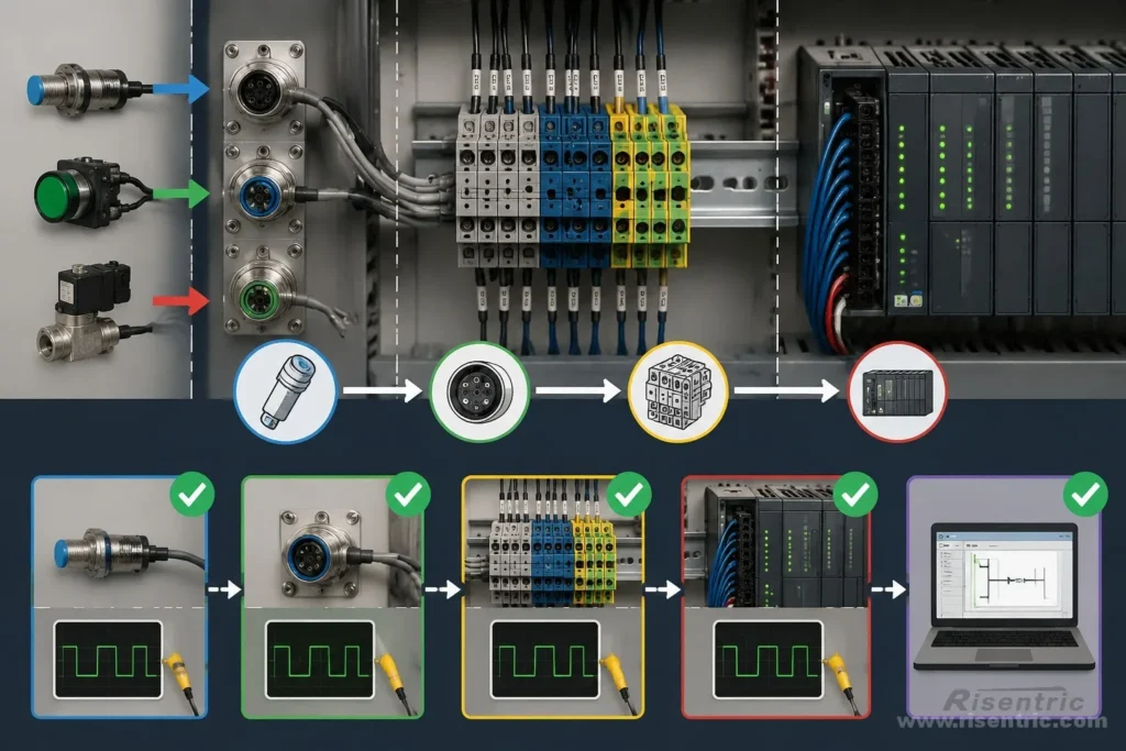
In a real drawing set, the PLC page is only one part of the full system.
For example, one control panel drawing set may include separate pages for:
| Sheet | What It Shows |
|---|---|
| Power Circuit | Main power wiring |
| Control Circuit | Control power and control devices |
| Servo Control | Servo drive, motor, encoder, brake, and control signals |
| PLC | PLC CPU, I/O terminals, HMI connection |
| Relay | Relay module and related control wiring |
| Loop Connector | Connector wiring between panel and field loop |
| Machine Connector | Machine-side sensors, switches, and wiring |
| Terminations | External connection points |
This kind of drawing should be read by signal path, not only by page title.
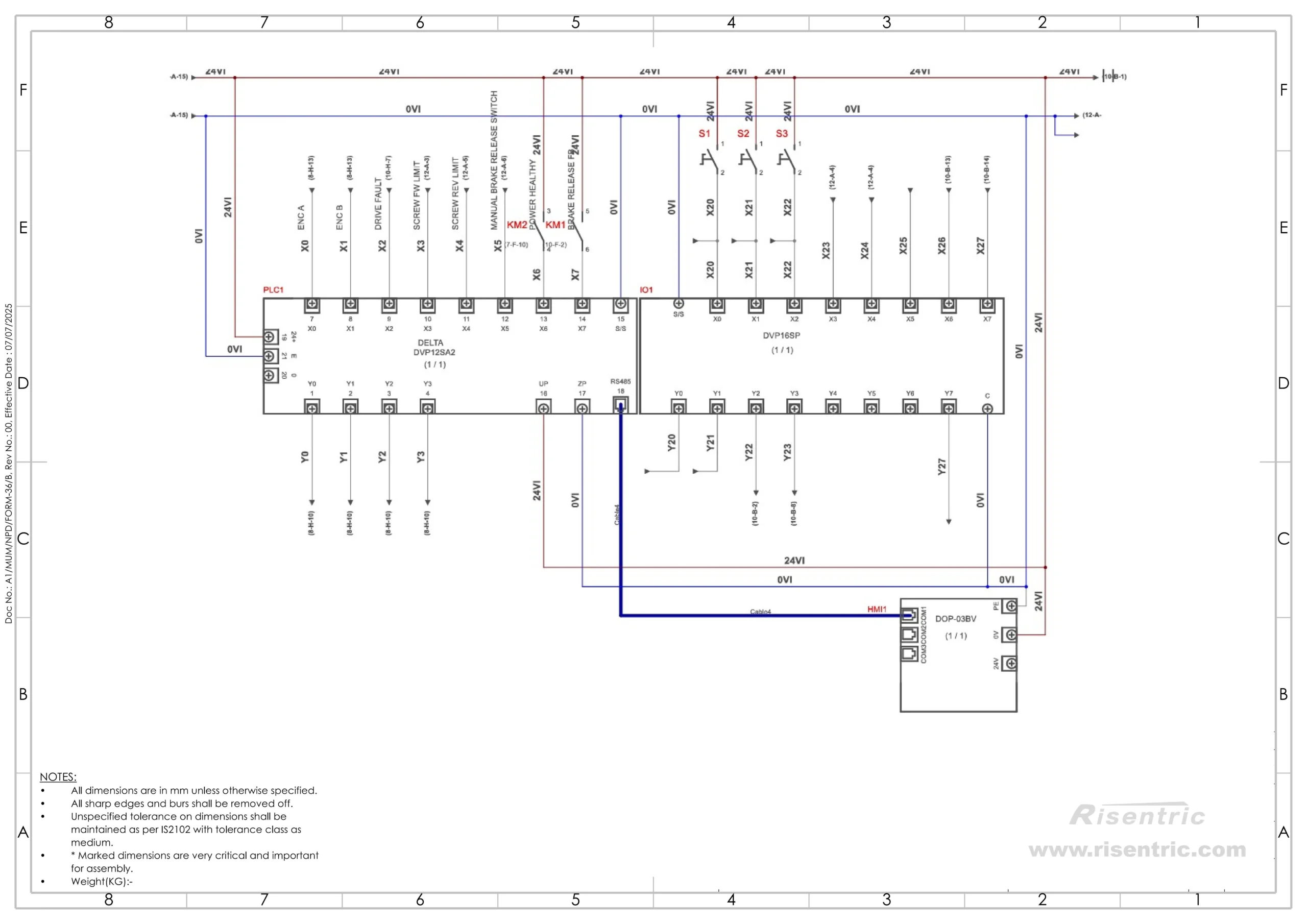
Example: Reading the PLC Page
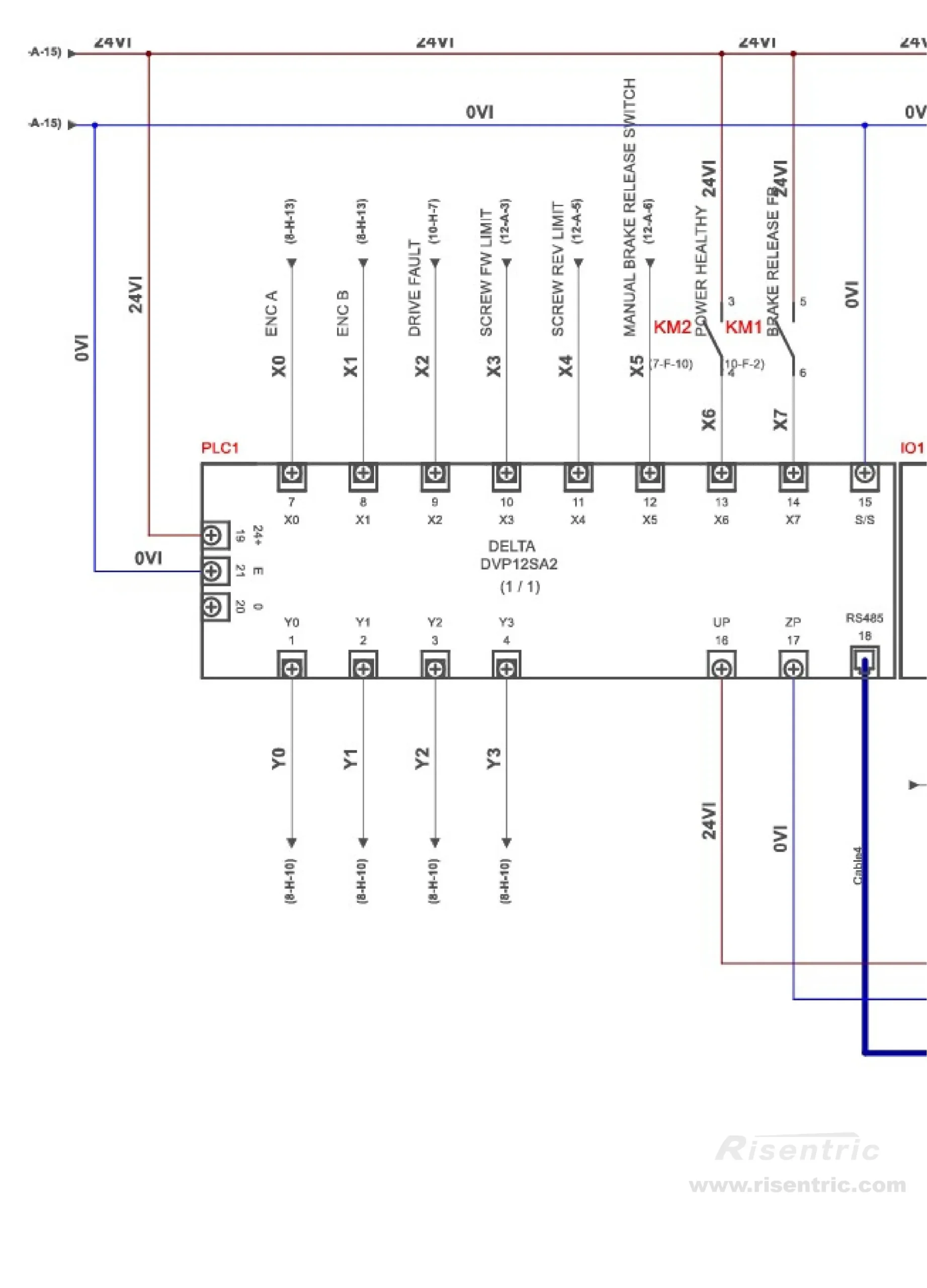
Start from the PLC sheet
-Module DELTA DVP12SA2.
The PLC page shows the controller, I/O terminals, 24 VDC / 0 VDC wiring, and connections to other devices.
- X0, Y0 above the line → Line No.
- X terminal → Usually PLC input
- Y terminal → Usually PLC output
- 24V → Control power positive
- 0V → Control power common
In above drawing, it is module DELTA DVP12SA2. In the below section, we will show model DVP16SP.
| Item | DELTA DVP12SA2 | DVP16SP |
|---|---|---|
| Role | Main PLC CPU / controller | Expansion I/O module |
| Can run PLC program? | Yes | No |
| Function | Executes logic, communicates with HMI/servo/other devices, controls I/O | Adds more input/output terminals |
| Typical terminals | X inputs, Y outputs, RS485, high-speed / special terminals | Extra X inputs and Y outputs |
| Used for | Main control logic | More field signals when CPU I/O is not enough |
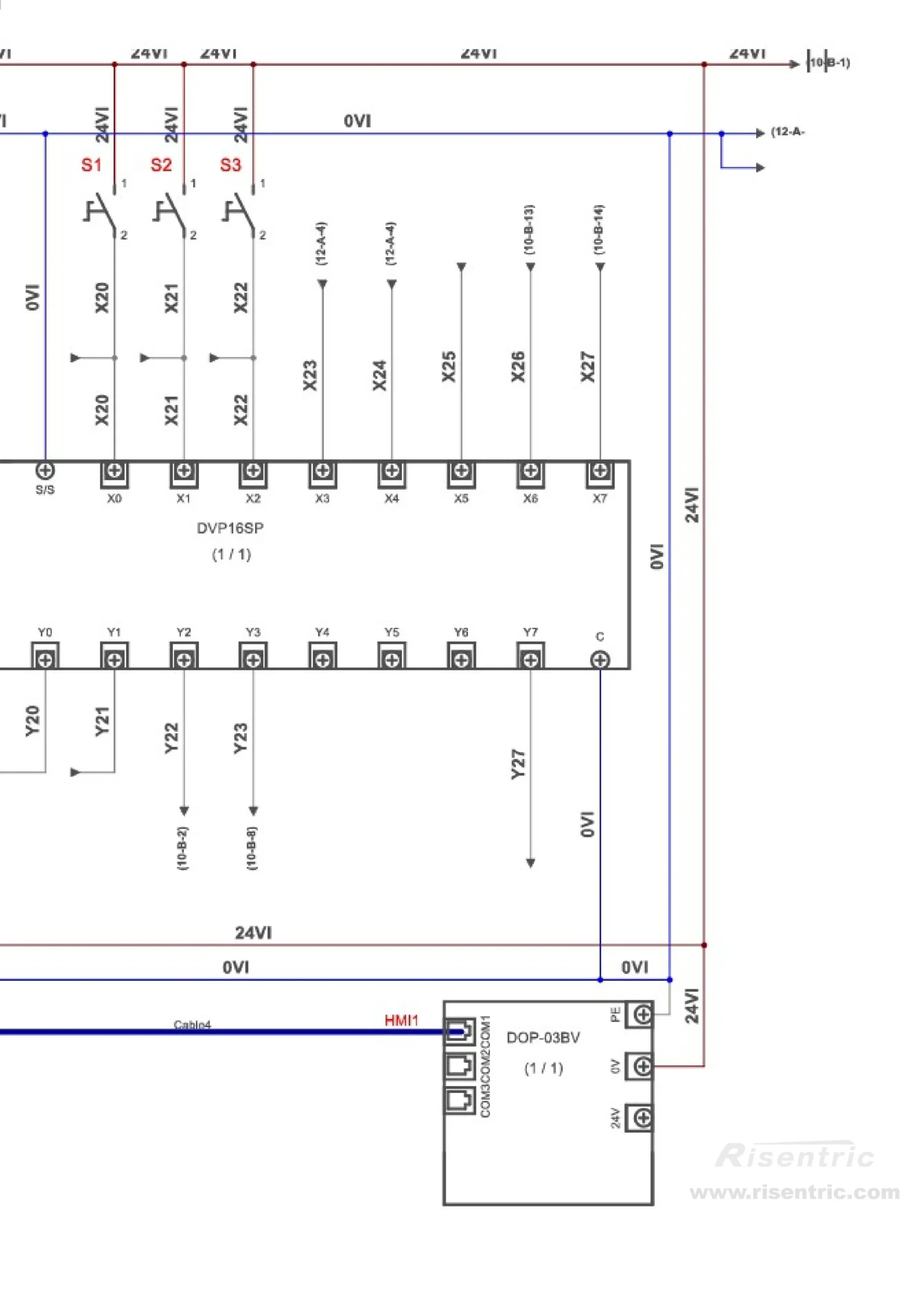
-Module DELTA DVP12SA2.
S1, S2, S3 → Switch contact
A switch contact may be manual or condition-operated, while a KM contact usually follows an electrically operated contactor or relay coil.
- DOP-03BV → HMI / touch panel
- COM1 → Communication ports
Together, these sections show how the PLC page is built: main PLC CPU, expansion I/O module, HMI connection, power supply, inputs, and outputs.
As shown below:
To summarize how to read the PLC Wiring Diagram:
The first step is to identify input and output terminals.
Then read each signal as a path.
Example:
field signal → connector / terminal block → PLC X input
or:
PLC Y output → relay / drive / connector → field action
The PLC page tells you the I/O point.
It does not always show the full field device.
*So if the signal continues to another sheet, follow the wire number or cross-reference.
Live Detail: Reading Contactor Feedback as PLC Input
A PLC wiring diagram is often built from small conditions.
This example shows several 24 VDC digital input signals going into the PLC.
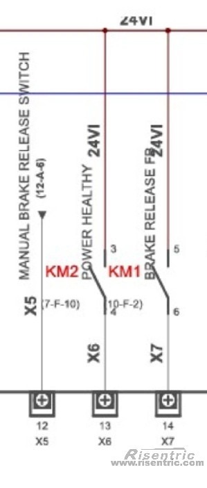
- At the top, there is a 24V control power line. At the bottom, the signals go into PLC input terminals such as X5, X6, and X7.
- In the middle, there are contacts marked with tags such as KM1 and KM2. These are contactor or relay contacts used to tell the PLC whether a condition is true.
Interpretation:
| PLC Input | Signal Name | How to Read It |
|---|---|---|
| X5 | Manual Brake Release Switch | A manual switch condition enters the PLC |
| X6 | Power Healthy | A contact closes when power condition is healthy |
| X7 | Brake Release FB | A feedback contact closes when brake release is confirmed |
The working path is:
24V → contact / switch → PLC input X terminal → PLC program
For example, for Power Healthy:
24V → KM2 auxiliary contact → X6
If power healthy condition is good → KM2 contact closes
If the KM2 contact closes → 24V reaches PLC input X6 → The PLC then reads this input as ON.
So the PLC program can understand:
X6 = ON → power healthy condition is true
*This assumes the KM2 auxiliary contact is normally open and closes when the power healthy condition is active. If the contact is normally closed, or if the PLC program uses inverted logic, the meaning of X6 may be different.
For Brake Release FB:
24V → brake release feedback contact → PLC input X7
If the brake release condition is confirmed → the feedback contact closes.
When this contact closes → 24V reaches PLC input X7 → The PLC then reads X7 as ON.
So the PLC program can understand:
X7 = ON → Brake Release feedback is received
However, the exact meaning depends on where the feedback contact comes from. If it is an auxiliary contact of a relay or contactor, it only confirms that the relay/contact has operated. If it comes from the brake mechanism or a brake status sensor, it can more directly confirm the actual brake release condition.
The key of these feedback design is: A PLC output may command something to happen, but the PLC still needs input feedback to know whether it actually happened.
For example:
| Command | Feedback | Meaning |
|---|---|---|
| Command ON | X7 ON | Brake release confirmed |
| Command ON | X7 OFF | Command sent, but no feedback |
| Command OFF | X7 ON | Abnormal feedback or wiring issue |
This is the key idea behind many PLC control circuits.
The PLC is not only sending commands. It is also checking conditions before and after the command.
How to Read Digital I/O and Analog I/O
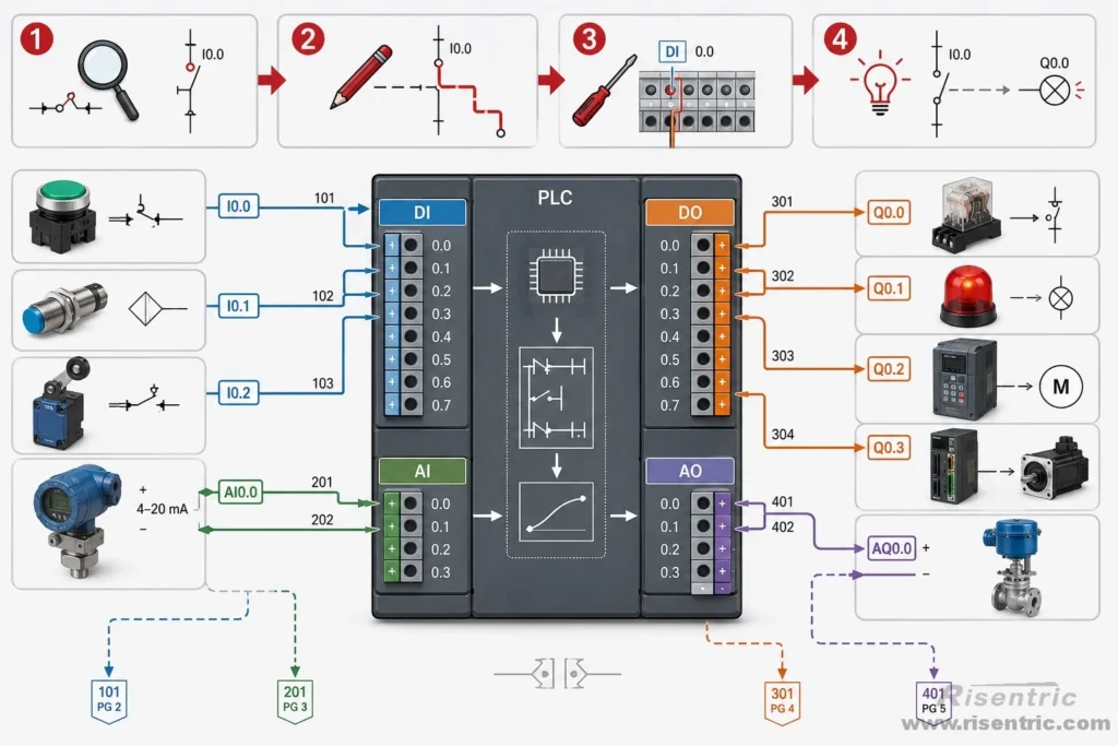
Most PLC wiring signals fall into four groups:
| Signal Type | Meaning | Direction |
|---|---|---|
| DI | Digital input | Field device → PLC |
| DO | Digital output | PLC → field device |
| AI | Analog input | Field device → PLC |
| AO | Analog output | PLC → field device |
When reading any PLC I/O circuit, ask:
| Question | Why It Matters |
|---|---|
| Is this DI, DO, AI, or AO? | Defines the signal type |
| Where does the signal start? | Finds the source |
| Where does the signal end? | Finds the destination |
| What terminal does it use? | Confirms the physical connection |
| What does the signal mean? | Connects wiring to control logic |
| Does it need common, 0V, or shield? | Confirms the complete circuit |
How to Read Digital Input Wiring
A digital input is a 1 or 0 signal entering the PLC.
It answers a yes/no question.
| Field Question | PLC Signal |
|---|---|
| Is the start button pressed? | DI |
| Is the emergency stop released? | DI |
| Is the contactor closed? | DI |
| Has the overload tripped? | DI |
| Is the VFD in fault? | DI |
The reading path is usually:
field contact → terminal block → PLC DI terminal → PLC program
Example:
contactor auxiliary contact → terminal block → PLC DI
This tells the PLC whether the contactor is actually closed.
When reading DI wiring, check:
| Item | What to Check |
|---|---|
| Field device | Which contact or switch sends the signal? |
| Contact type | Normally open or normally closed? |
| Input voltage | Commonly 24 VDC, but must be confirmed |
| PLC terminal | Which DI terminal receives the signal? |
| Common / 0V | Is the input common wired correctly? |
| Signal meaning | Does DI = 1 mean normal, fault, open, closed, start, or stop? |
Important point:
Do not only read “DI3.” Read what DI3 means.
For example:
DI3 = VFD fault is useful information.
DI3 alone is only a PLC address.
How to Read Digital Output Wiring
A digital output is also a 1 or 0 signal, but it leaves the PLC.
It is a command.
| PLC Command | Output Type |
|---|---|
| Start motor | DO |
| Energize relay | DO |
| Turn on alarm lamp | DO |
| Reset VFD fault | DO |
| Open solenoid valve | DO |
The reading path is usually:
PLC DO terminal → relay / contactor / VFD terminal → field action
Example:
PLC DO → interface relay → contactor coil
This means the PLC does not directly power the motor. It sends a control command. The relay, contactor, VFD, or MCC circuit performs the actual switching.
When reading DO wiring, check:
| Item | What to Check |
|---|---|
| PLC output terminal | Which DO terminal sends the command? |
| Output type | Relay output or transistor output? |
| Load device | Relay coil, contactor coil, VFD input, lamp, buzzer, solenoid |
| Control voltage | 24 VDC, 110 VAC, 230 VAC, etc. |
| Protection | Fuse, diode, relay isolation, or interposing relay |
| Feedback | Is there a DI signal proving the command worked? |
Important point:
A DO command does not prove the equipment actually operated.
Example:
PLC DO → contactor coil
contactor auxiliary contact → PLC DI feedback
Then the PLC can compare command and feedback:
| DO Command | DI Feedback | Meaning |
|---|---|---|
| DO = 1 | DI = 1 | Command worked |
| DO = 1 | DI = 0 | Command sent, but no feedback |
| DO = 0 | DI = 1 | Abnormal feedback or wiring problem |
This is a very common pattern in motor control panels.
How to Read Analog Input Wiring
An analog input is a changing value entering the PLC.
It is not only 1 or 0.
Common analog input signals include:
- pressure
- temperature
- level
- flow
- pH
- current
- voltage
- speed feedback
The reading path is usually:
sensor / transmitter → terminal block → PLC AI terminal → PLC program
Example:
pressure transmitter → 4–20 mA → PLC AI
The PLC analog input module converts the analog signal into digital data. This is called A/D conversion.
The process is:
analog signal → AI module → digital numerical value → PLC program
Example:
| Pressure | Signal | PLC Meaning |
|---|---|---|
| 0 bar | 4 mA | Minimum value |
| 5 bar | 12 mA | Middle value |
| 10 bar | 20 mA | Maximum value |
This does not mean analog input becomes digital input.
A digital input is a physical ON/OFF terminal.
An analog input becomes a numerical value inside the PLC program.
When reading AI wiring, check:
| Item | What to Check |
|---|---|
| Signal source | Which transmitter or sensor sends the value? |
| Signal type | 4–20 mA, 0–10 V, RTD, thermocouple, etc. |
| PLC AI support | Does the analog module support this signal type? |
| Positive / negative | Are signal polarity and common correct? |
| Shielding | Is shielded cable required? |
| Scaling | What engineering value does the signal represent? |
Example:
4–20 mA = 0–10 bar
If the PLC receives 12 mA, the program may read about 5 bar.
Then the PLC can create internal logic:
pressure < 3 bar → pressure low = TRUE
But “pressure low” is an internal logic result. It is not a physical DI terminal.
How to Read Analog Output Wiring
An analog output is a changing command leaving the PLC.
It is commonly used for:
- VFD speed reference
- valve opening control
- damper position control
- pressure control
- flow control
The reading path is usually:
PLC AO terminal → field device analog input → controlled action
Example:
PLC AO → 0–10 V / 4–20 mA → VFD analog input
The PLC program calculates a command value first. Then the analog output module converts that internal value into a real analog signal. This is called D/A conversion.
The process is:
PLC program value → AO module → analog signal → VFD / valve / field device
Example for VFD speed control:
| PLC Speed Command | AO Signal | VFD Meaning |
|---|---|---|
| 0% | 0 V / 4 mA | Minimum speed |
| 50% | 5 V / 12 mA | Medium speed |
| 100% | 10 V / 20 mA | Full speed |
When reading AO wiring, check:
| Item | What to Check |
|---|---|
| PLC AO terminal | Which AO channel sends the signal? |
| Signal type | 0–10 V or 4–20 mA? |
| Field device input | Does the VFD or valve accept the same signal type? |
| Common terminal | Is analog common connected correctly? |
| Shielding | Is shielded cable used if required? |
| Parameter setting | Is the VFD or device configured for the same signal type? |
| Scaling | What does 0%, 50%, or 100% mean in the field device? |
Important point:
Analog output wiring is not enough by itself. The field device parameter must also match the signal.
For example, if the PLC sends 4–20 mA, but the VFD is set to read 0–10 V, the speed command will not work correctly.
What the Wiring Diagram Does Not Tell You
A wiring diagram tells you how devices are connected.
It does not fully tell you the PLC program logic.
From the wiring diagram, you can understand:
- which signal enters the PLC
- which output leaves the PLC
- which terminal is used
- which relay, connector, or field device is connected
- how the circuit is physically wired
But the wiring diagram usually does not show:
- ladder logic
- function block logic
- timers
- counters
- interlock sequence
- alarm rules
- servo motion sequence
- HMI screen logic
So the difference is:
Wiring diagram = how devices are connected
PLC program = when and why the PLC acts
To fully understand the control behavior, you need both the wiring diagram and the PLC program or control sequence description.
Looking for factory-tested 3-Phase switchgear & Panel boards for your project?
Conclusion
For each signal, ask:
Is it DI, DO, AI, or AO?
Where does it start?
Where does it go?
What terminal does it use?
What does the signal mean?
A good PLC wiring diagram makes every signal easy to trace from the field device to the PLC, and from the PLC back to the controlled equipment.
FAQ
What is the purpose of a PLC wiring diagram?
A PLC wiring diagram shows how field devices, PLC terminals, relays, connectors, sensors, drives, and control power are physically connected. It helps engineers trace signals entering and leaving the PLC.
What is the difference between DI and DO?
DI, or digital input, is a 1/0 signal entering the PLC.
DO, or digital output, is a 1/0 command leaving the PLC.
What is the difference between AI and AO?
AI, or analog input, is a changing value entering the PLC, such as pressure, level, temperature, or flow.
AO, or analog output, is a changing command leaving the PLC, such as a VFD speed reference.
Does analog input become digital input inside the PLC?
No. Analog input becomes digital numerical data, not a physical digital input.
For example:
4–20 mA → A/D conversion → pressure value in PLC program
The PLC program may then compare this value with a setpoint and create an internal logic condition.


