
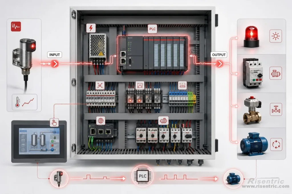
A PLC control panel may look complicated from the outside. There may be a CPU, I/O modules, terminals, relays, communication ports, HMI, and MCC connections inside the cabinet.
But the basic idea is simple.
A PLC control panel allows one part of a system to react automatically according to the condition of another part:
- A sensor detects a condition.
- The PLC processes the information.
- Another device receives the command and takes action.
This article explains the structure of a PLC control panel from this practical point of view: how field signals enter the panel, how the PLC understands them, and how the system turns those signals into automatic control.
Why Do we Need a PLC?
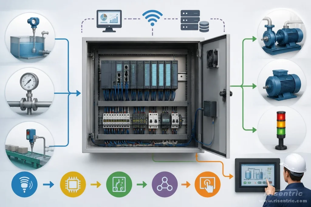
The basic reason for using a PLC is simple:
A PLC allows one part of a system to react automatically according to the condition of another part.
For example:
- If the water level is low, start the pump.
- If the pressure is too high, stop the motor.
- If one machine is not ready, prevent the next machine from starting.
Without a PLC, many of these actions would need to be done manually or by complicated relay logic.
With a PLC, the system can collect signals, judge conditions, and send commands automatically.
This is the real purpose of the PLC control panel.
The components inside the panel are all used to achieve this goal.
- Inputs — to know what is happening
- CPU / program — to decide what should happen
- Outputs — to make something happen
- Communication — to exchange more complex information
- HMI — to let people monitor or change settings
- MCC integration — to control real motor power equipment
Key Parts of a PLC Control Panel
To understand how a PLC control panel works, it is useful to look at the main parts inside the system.
Main PLC CPU
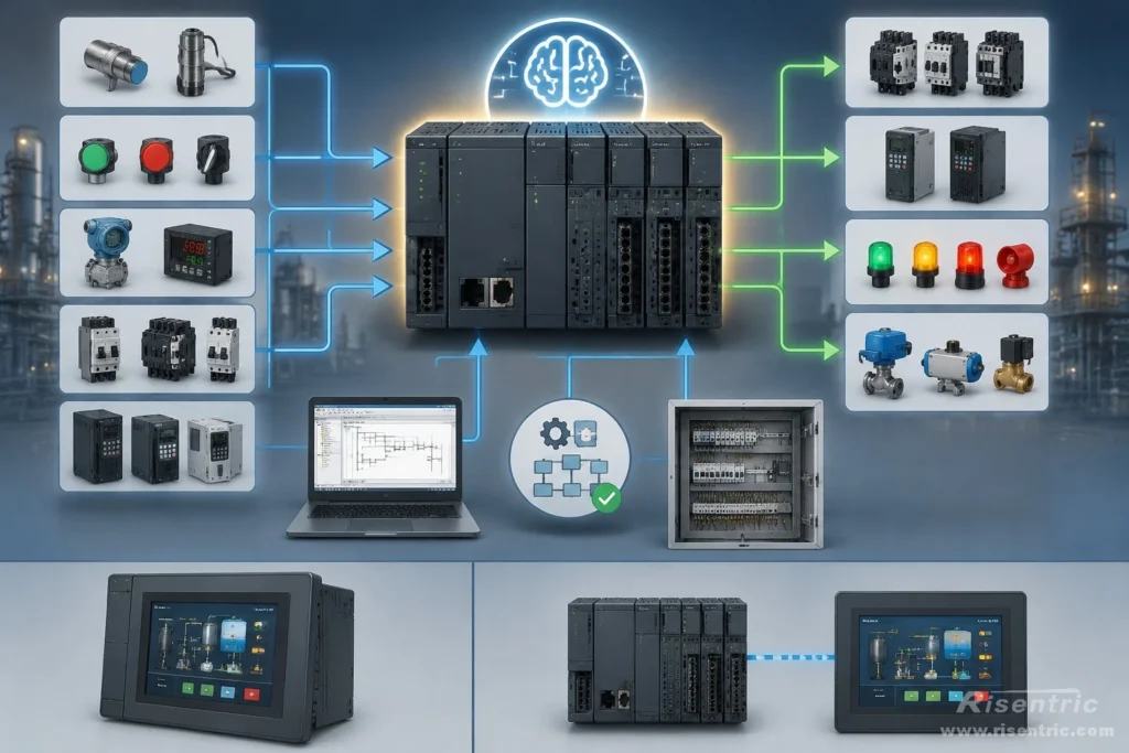
The PLC CPU is the brain of the control panel.
It is similar to the CPU in a laptop or computer. A laptop CPU receives information from the keyboard, mouse, storage, and software, processes it, and then produces a result on the screen or through another device.
A PLC CPU works in a similar way, but for industrial control.
It receives input information from sensors, switches, instruments, MCC feeders, VFDs, and other field devices. Then it processes this information according to the PLC program. After checking the logic, it sends output commands to relays, contactors, VFDs, lamps, alarms, valves, or other equipment.
For example, if a level sensor tells the PLC that the water level is low, the CPU checks the program logic. If the system is in automatic mode, the breaker is closed, there is no fault, and the pump is allowed to run, the PLC CPU sends a start command to the MCC or VFD.
So the CPU does three important things:
- It receives information from the field.
- It makes decisions according to the program.
- It sends commands to make the system react.
In some compact PLC systems, the CPU and HMI may be built into the same device. In other systems, the CPU is only the controller, while the HMI is installed separately on the panel door.
For panel design, the CPU is important because it determines the control platform, programming software, communication options, expansion capacity, and how the whole control system will be structured.
Digital I/O Section
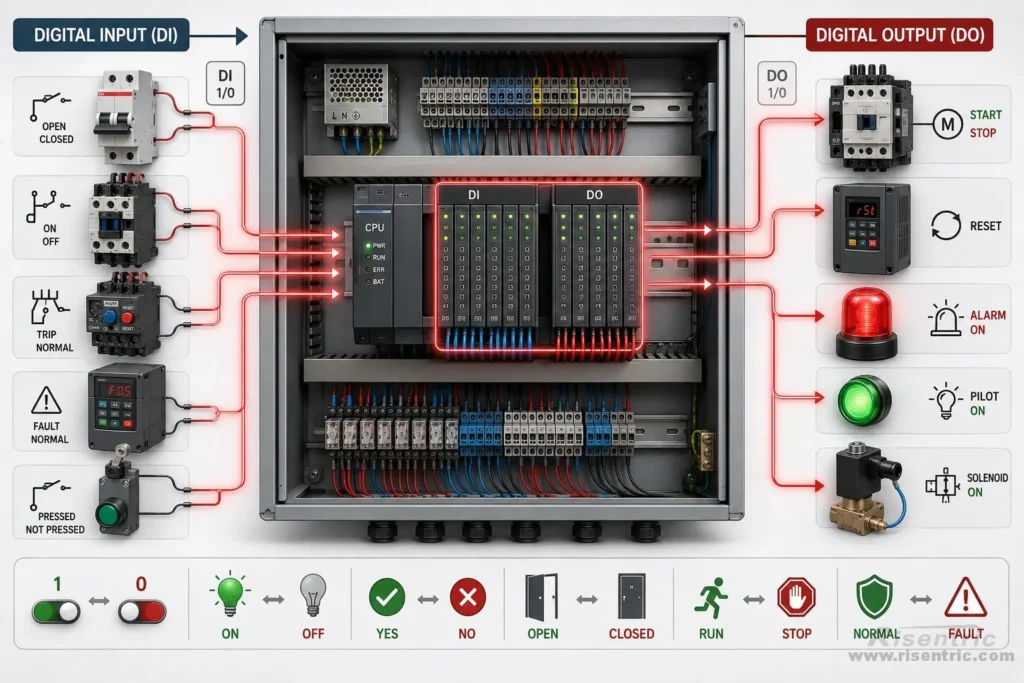
Digital I/O is used for simple ON/OFF signals.
It is called digital because the signal has only two states:
1 or 0
ON or OFF
Yes or No
Open or Closed
Running or Stopped
Fault or Normal
In other words, digital I/O does not describe a changing value like pressure, temperature, or speed. It only tells the PLC whether a condition exists or not.
A digital input is a signal received by the PLC.
For example, the PLC may receive these signals:
- Breaker closed or open
- Contactor running or stopped
- Overload trip or normal
- VFD fault or normal
These signals help the PLC understand the current condition of the system.
A digital output is a command sent by the PLC.
For example, the PLC may send these commands:
- Start the motor
- Stop the motor
- Reset the fault
- Turn on an alarm lamp
So digital I/O is the basic signal language between the PLC and the field devices.
The field device tells the PLC a condition with 1 or 0.
The PLC sends a command back with 1 or 0.
Analog I/O Section
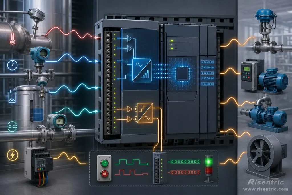
Analog I/O is used for signals that change continuously.
Digital I/O is simple: it is only 1 or 0, ON or OFF.
Analog I/O is different. It is used when the PLC needs to understand a changing real-world condition, such as temperature, pressure, level, flow, current, voltage, or speed.
A good example is a temperature sensor such as an RTD or thermistor.
The sensor itself does not really “know” the temperature. It does not directly send the PLC a message saying “the temperature is 60°C.” Instead, the physical condition changes first.
When the temperature changes, the resistance of the sensor changes. This resistance change is an analog condition. It can move continuously, not only between two fixed states.
The analog input module measures this electrical change. Inside the module, an A/D converter converts the analog signal into a digital number. The PLC CPU then receives this number and uses it in the control program.
In simple terms:
Temperature change → resistance change → analog measurement → A/D conversion → digital number inside the PLC
After this, the PLC program or module configuration can scale the number into a real engineering value, such as 35°C, 60°C, or 90°C.
So analog input is not only “reading temperature.” More accurately, it is converting a real physical change into a number that the PLC CPU can understand.
In simple terms:
Analog input helps the PLC understand changing real-world conditions.
Analog output helps the PLC control equipment with variable output.
Communication Section
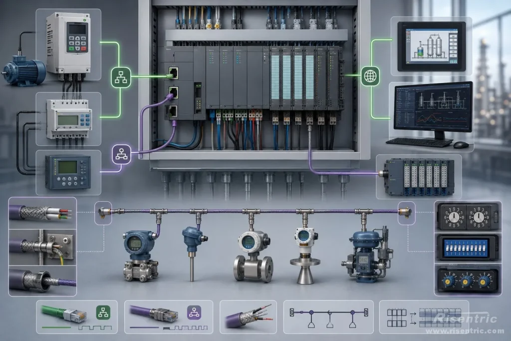
Not every signal is hardwired.
A PLC may communicate with VFDs, energy meters, protection relays, remote I/O modules, instruments, HMI, or SCADA systems through communication.
Common communication methods include Ethernet, RS485, Modbus RTU, Modbus TCP, Profinet, Profibus, and other industrial protocols.
For example, RS485 may be used for communication with meters, VFDs, or instruments.
However, communication is not only a hardware question. The protocol, address, baud rate, register map, shielding, and termination must also be confirmed.
HMI / Operator Interface
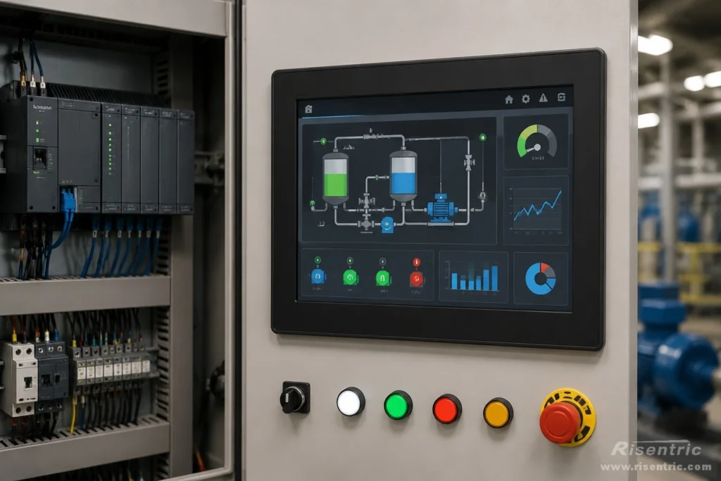
Some PLC systems have a built-in operator screen. Others need a separate HMI installed on the panel door.
The HMI allows operators to view system status, alarms, running mode, motor status, setpoints, and fault information.
For a control panel, it is important to confirm whether the HMI is required, whether it is built into the PLC, and what information the operator needs to see or adjust.
Terminal Blocks and Field Wiring
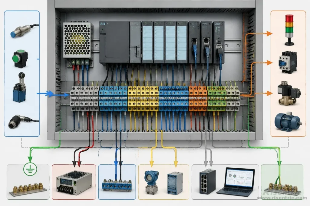
Terminal blocks are like the ports of a PLC control panel.
Field signals do not usually connect directly to the PLC modules. They first enter the panel through terminal blocks. From there, internal wires connect the signals to the PLC inputs, outputs, power supply, relays, or communication devices.
So terminal blocks are the entry and exit points of the control panel.
For example:
- Sensor signals enter the panel through terminal blocks.
- PLC output commands leave the panel through terminal blocks.
- 24 VDC power can be distributed through terminal blocks.
- Communication cables can also connect through terminal blocks.
This makes wiring clearer and easier to check.
If there is a problem on site, the engineer can test the signal at the terminal block first. This helps confirm whether the problem is outside the panel, inside the panel, or inside the PLC.
For a PLC panel, terminal blocks should be arranged clearly for digital inputs, digital outputs, analog signals, communication cables, power, 0 V common, and grounding.
In simple terms:
Terminal blocks are the connection ports between the PLC panel and the outside field devices.
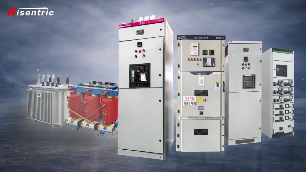
Looking for factory-tested 3-Phase switchgear & Panel boards for your project?
PLC and MCC Integration
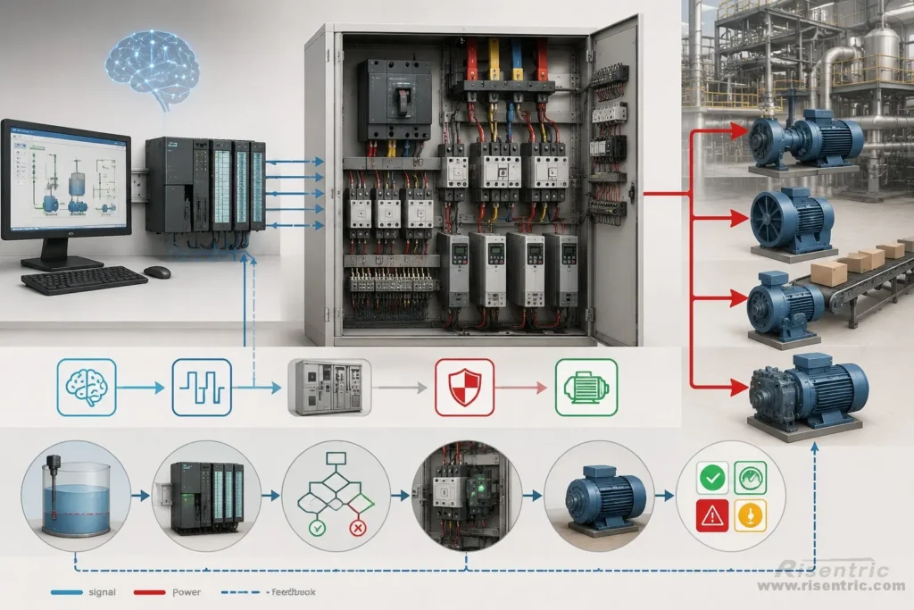
Motors are one of the most widely used devices in industrial systems.
Pumps, fans, compressors, conveyors, mixers, crushers, blowers, and many production machines are driven by motors. In many factories, water systems, HVAC systems, and process lines, the motor is the final device that actually makes movement happen.
This is why motors are one of the most common devices controlled by a PLC.
If we compare an automated system to a human body, the PLC is like the brain and nervous system. It receives information, processes logic, and sends commands. The motor is like the hand or muscle. It performs the real action.
However, the PLC cannot directly power a motor.
A motor usually needs high current, short-circuit protection, overload protection, starting control, and sometimes speed control. These functions are handled by the MCC, or Motor Control Center.
The MCC is the power and protection side of motor control. It may include:
- Circuit breakers
- Contactors
- Overload relays
- Soft starters
- VFDs
- Motor protection devices
- Power terminals
- Control terminals
The PLC is the logic and signal side. It decides when the motor should start, stop, alarm, reset, or change speed.
So the relationship is simple:
The PLC decides what should happen.
The MCC safely carries out the motor power operation.
The motor performs the actual work.
For example, in a pump system, the PLC may receive a low water level signal. The PLC checks the logic: Is the system in automatic mode? Is the breaker closed? Is there no overload trip? Is the VFD healthy? If all conditions are correct, the PLC sends a start command to the MCC.
The MCC then starts the motor through a contactor, soft starter, or VFD. After the motor starts, the MCC sends feedback signals back to the PLC, such as motor running, overload trip, VFD fault, or local / remote status.
Different PLC Structures, Same Control Purpose
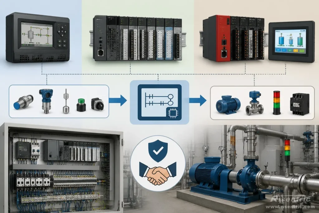
PLC systems do not always look the same.
Different brands may use different CPUs, I/O modules, expansion methods, communication modules, and HMI designs. Some PLCs are compact and have the CPU, I/O, and screen built into one device. Some PLCs are modular, with separate CPU, digital I/O, analog I/O, communication modules, and HMI.
The structure may be different, but the purpose is the same:
receive conditions, process logic, and send commands.
This is also why PLC configuration is not always about using the most powerful controller. In many industrial control systems, the goal is not to use a computer with the highest performance. The goal is to use a controller that is stable, compact, easy to maintain, and good enough to complete the required control function.
A PLC is different from a normal computer.
A computer is powerful and flexible, but it is not always the best choice for industrial control. A PLC is designed for industrial environments. It can run simple control logic for a long time, handle field signals directly, work with 24 VDC control circuits, connect with sensors and actuators, and operate reliably inside a control panel.
In many real projects, the PLC does not need to do complicated calculation. It only needs to answer practical control questions:
- Is the water level low?
- Is the motor ready?
- Is the VFD healthy?
- Is the system in automatic mode?
- Should the pump start?
- Should the alarm turn on?
- Should the equipment stop for protection?
For this kind of work, a simple and robust PLC system is often enough.
This is the philosophy behind many PLC control panels:
Enough is good. Stable is better than complicated.
The PLC does not need to be oversized if the control task is simple. What matters more is whether the I/O points are enough, the signal types are correct, the wiring is clear, the logic is reliable, and the system can operate safely for many years.
So when looking at a PLC control panel, do not only focus on the brand or model number. The more important question is:
Can this PLC structure receive the required signals, process the logic, and control the equipment reliably?
If the answer is yes, then the PLC configuration may already be suitable for the project.
Looking for factory-tested 3-Phase switchgear & Panel boards for your project?
Conclusion
In simple terms, a PLC control panel turns signals into automatic control.
The PLC is the brain and nervous system of the control panel.
The field devices provide information.
The MCC and motors perform the action.
A PLC does not need to be the most powerful device. It needs to be stable, compact, robust, and enough for the required control function.
For many industrial systems, enough is good. Indeed, the same idea can apply to life and nature.
FAQ
What is the main purpose of a PLC control panel?
The main purpose of a PLC control panel is to make a system react automatically.
It receives signals from field devices, processes the logic inside the PLC program, and sends commands to other equipment.
Why use a PLC instead of manual control?
Manual control depends on people.
A PLC can monitor signals and react automatically. For example, if the water level is low, the PLC can start a pump. If a fault occurs, the PLC can stop equipment and trigger an alarm.
Why is the PLC CPU called the brain of the panel?
The PLC CPU receives information, processes logic, and sends commands.
This is similar to how a brain receives information from the body, makes decisions, and sends instructions to muscles.
What is digital I/O in a PLC?
Digital I/O is used for simple ON/OFF signals.
It only has two states, such as 1 or 0, running or stopped, fault or normal, open or closed.
What is analog I/O in a PLC?
Analog I/O is used for changing values.
It helps the PLC understand real-world conditions such as temperature, pressure, level, flow, current, voltage, or speed.
Does the PLC receive temperature directly?
Not always.
For example, a temperature sensor may only change its resistance when temperature changes. The analog input module measures this change and converts it into a digital number. After processing, the PLC can use it as a temperature value.
What is the role of terminal blocks in a PLC panel?
Terminal blocks are the connection ports of the PLC control panel.
Field signals enter the panel through terminal blocks, and PLC output commands leave the panel through terminal blocks.
Why does a PLC connect with an MCC?
Motors are widely used in industrial systems.
The PLC decides when a motor should start, stop, reset, or change speed. The MCC handles the motor power, protection, contactors, overload relays, soft starters, or VFDs.
Does the PLC directly power the motor?
No.
The PLC sends control commands. The MCC or motor starter equipment handles the actual motor power.


