
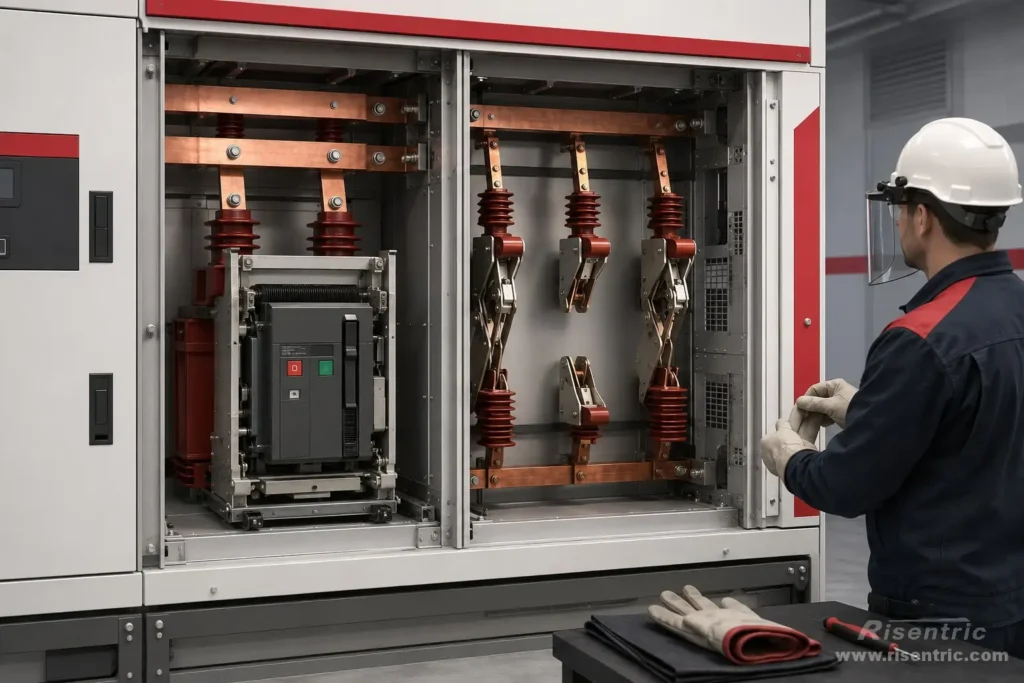
In switchgear drawings, the isolator is often confused with the circuit breaker.
But these devices have different jobs. A circuit breaker interrupts current, an isolator creates a physical separation gap.
The main purpose of an isolator is maintenance safety:
it creates a clear physical separation point after the circuit has already been switched off.
This article explains the actual structure of an isolator, where it is placed, and why it can change the design of MV switchgear.
What Is an Isolator in Switchgear?
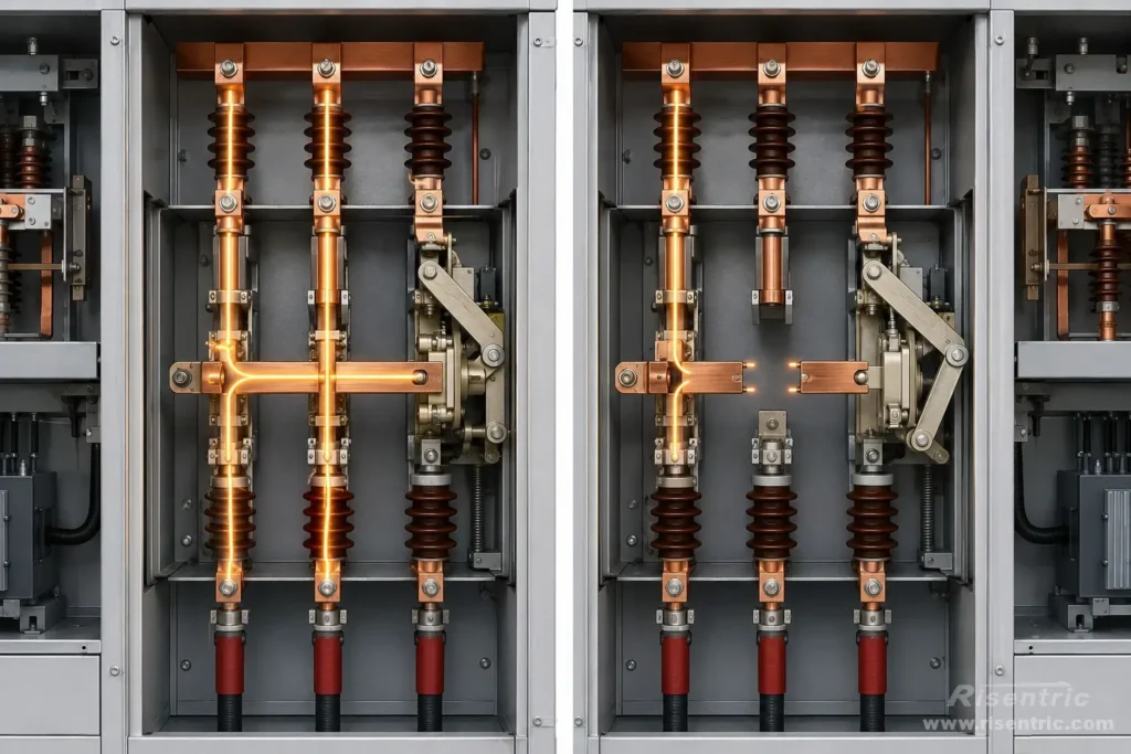
An isolator, also called a disconnector, is a device used to physically disconnect a circuit after the current has already been interrupted.
It is not mainly used to break load current or fault current. Its job is to create a safe separation point for inspection, maintenance, or switching operation.
An isolator does not protect the circuit. It creates a physical isolation gap.
Explain simply:
When the isolator is closed, the circuit has a continuous metal path:
Source → Metal Contact → Load
When the isolator is open, the metal path is separated and replaced by an insulation gap:
Source → Air Gap → Load
The current path is broken because part of the conductive path is mechanically moved away.
What Mechanism Is Used to Isolate the Circuit?
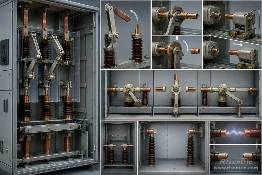
An isolator works by moving a conductive part away from another conductive part.
Common structures include:
| Mechanism Type | How It Works |
|---|---|
| Knife-blade type | A blade rotates away from the fixed contact |
| Rotary type | A rotating contact turns to connect or disconnect the circuit |
| Sliding / draw-out type | A moving contact is pulled away from a fixed contact |
| Three-position type | Closed, isolated, and earthed positions are combined |
The key point:
The isolator replaces a metal connection with an insulation gap.
But this gap must be large enough for the voltage level. Air normally does not conduct at rated voltage, but if the voltage is too high or the gap is too small, flashover can happen.
So the isolator is not just “cutting a wire.” It is a designed insulation structure with proper clearance, creepage distance, contact distance, and mechanical strength.
The mechanism also leads into the following section: when the voltage increase, the isolator will need more space for the isolation.
The Isolator Become Larger When Voltage Increases
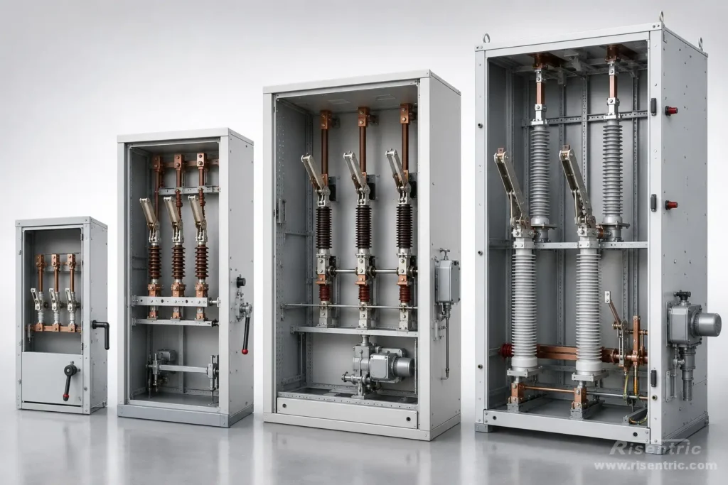
The size of an isolator is mainly affected by voltage because higher voltage needs a larger insulation distance.
At low voltage, the required air gap is small. At medium voltage, the required phase-to-phase and phase-to-earth clearance becomes much larger.
| Voltage Level | Size Impact |
|---|---|
| 400 V / 690 V LV | Compact switch-disconnector can fit inside LV panel |
| 11 / 12 kV MV | Larger contact gap and insulation supports are required |
| 24 kV MV | Larger phase spacing and cabinet clearance |
| 33 / 36 kV MV | Very large air-insulated structure; may change cabinet layout |
What affects the size:
- rated voltage
- rated current
- short-time withstand current
- phase-to-phase clearance
- phase-to-earth clearance
- open contact gap
- air-insulated or gas-insulated design
- whether earthing switch is integrated
- manual or motorized operating mechanism
The higher the voltage, the larger the air gap and insulation structure must be. This is why an MV isolator is not a small accessory inside the cabinet.
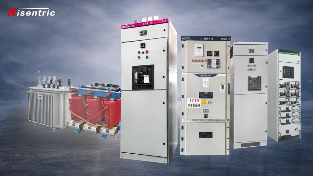
Looking for factory-tested 3-Phase switchgear & Panel boards for your project?
Where Is the Isolator Placed in the Circuit?
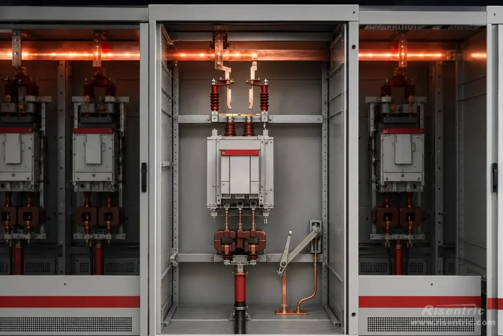
In fixed MV VCB switchgear
A common structure is:
Busbar → Isolator / Disconnector → Fixed VCB → CT → Cable Terminal → Earthing Switch
Here:
- the VCB interrupts current
- the isolator creates the isolation gap
- the earthing switch grounds the isolated side
Why the isolator is often placed between the busbar and the fixed circuit breaker?
The reason is safety and maintenance.
The busbar is the main power source inside the switchgear. When one feeder panel needs maintenance, the safest isolation point is usually at the beginning of that feeder branch, as close as practical to the energy source.
By opening the isolator at this position, the downstream parts of that feeder, including the fixed VCB, CT, cable terminal, and outgoing cable side, can be separated from the live busbar.
This is especially important because the purpose of an isolator is mainly maintenance isolation. In many switchgear systems, one feeder may need to be stopped while the other feeders should continue operating. The main busbar may remain energized, and only the selected branch is isolated.
So the isolator is not placed there randomly. It works like a cut point at the start of one branch.
How Does an Isolator Change the Switchgear Design?
Considering the size and where it located in the switchgear structure, adding an isolator in MV switchgear may change the whole cabinet structure.
So when an isolator is added, many other parts of the switchgear must be redesigned together.
1. Extra Space for the Main Isolation Device
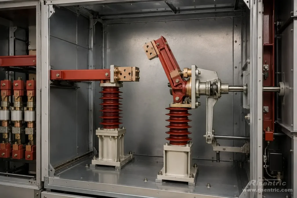
The isolator needs physical room for its fixed contacts, moving blade or rotary contact, insulators, operating shaft, and open contact gap. At medium voltage, this space is much larger than in low-voltage equipment because the air clearance between live parts must be maintained.
2. Revised Busbar and Copper Connections
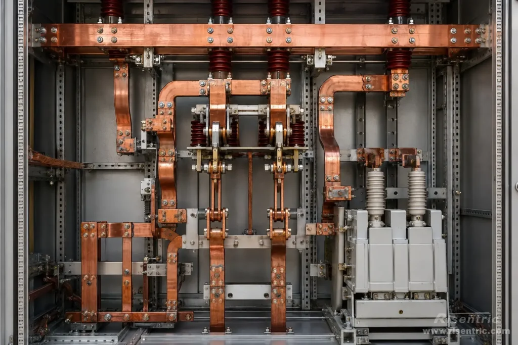
The isolator has to be connected between the busbar and the breaker, so the busbar and copper connection arrangement must change. Extra copper links, contact points, supports, and insulation parts may be required. These extra connection points also need to be checked for temperature rise and short-time withstand current.
3. Changed Internal Cabinet Layout
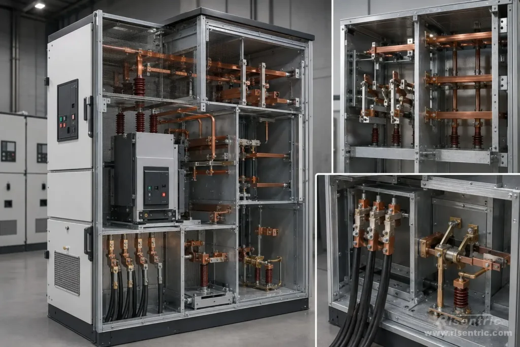
The position of the breaker, CT, cable terminal, earthing switch, and busbar compartment may need to be adjusted. In some designs, the cabinet height, depth, or width may increase. In other cases, the whole switchgear type may change from a standard withdrawable VCB design to a fixed VCB with disconnector design.
4. More Complicated Interlocking
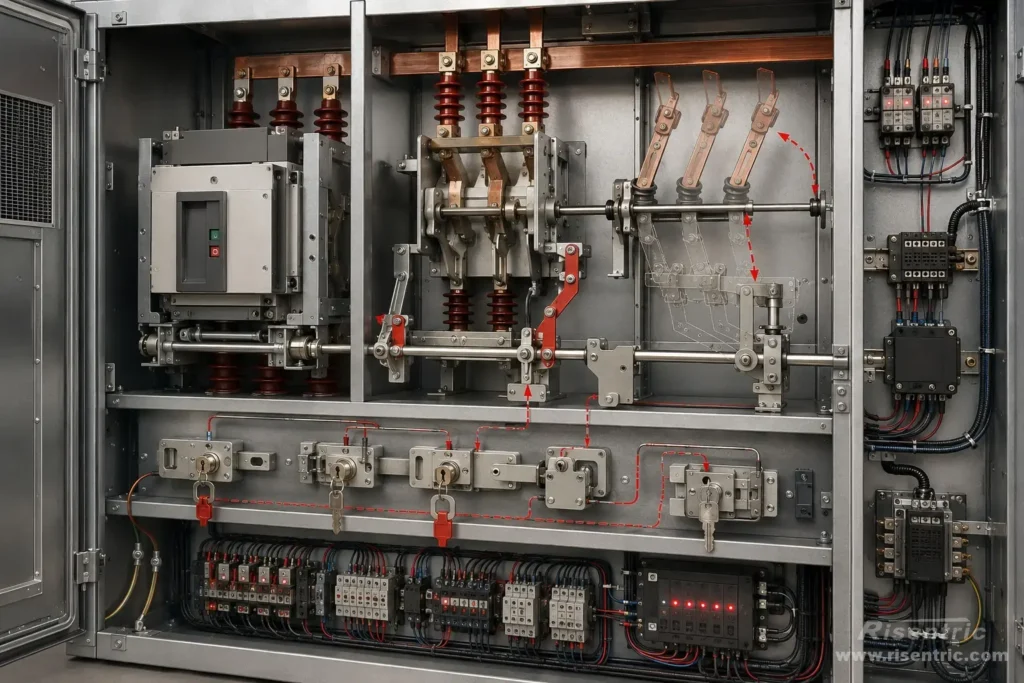
The breaker, isolator, and earthing switch must operate in the correct sequence. For example, the isolator should not be opened under load, and the earthing switch should not be closed when the circuit is live. This may require mechanical interlocks, key interlocks, position switches, and electrical interlock signals.
5. Additional Operating and Indication Mechanism
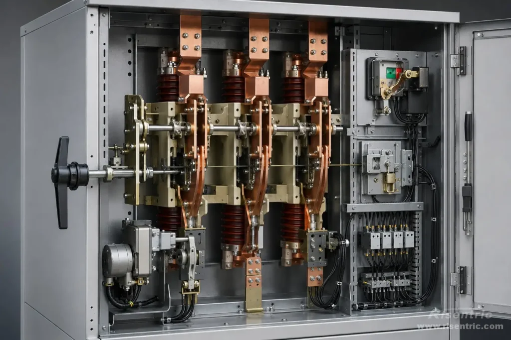
The isolator needs a manual or motorized operating mechanism, position indication, locking device, and sometimes auxiliary contacts for remote status feedback. These are not large compared with the main copper parts, but they still affect the panel structure and control wiring.
| Design Area | Effect |
|---|---|
| Cabinet size | More height, width, or depth may be required |
| Busbar arrangement | Extra connection points and supports are needed |
| Internal clearance | Phase-to-phase and phase-to-earth distance must be maintained |
| Interlocking | Breaker, isolator, and earthing switch must be coordinated |
| Cost | Extra device, copper, mechanism, and engineering |
| Delivery time | Custom layout may require longer production |
It is not just “one more part.” It may become a different switchgear design.
When Is an Isolator Useful? When is not?
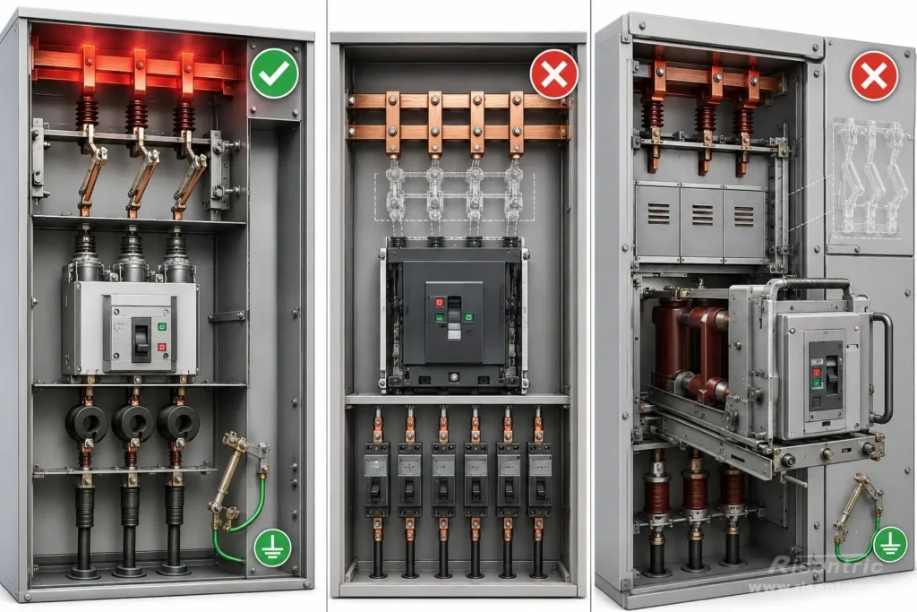
An isolator is useful when the switchgear needs a clear physical isolation point for maintenance. But whether a separate isolator is needed depends on the switchgear structure.
1. Fixed MV VCB Switchgear
In fixed medium-voltage VCB switchgear, the breaker is fixed inside the cabinet. It cannot be withdrawn to create an isolated position.
A common arrangement is:
Busbar → Isolator / Disconnector → Fixed VCB → CT → Cable Terminal
Earthing switch: connected on the cable side to earth
In this structure, the VCB interrupts load current and fault current. The isolator creates a physical isolation gap from the busbar side. The earthing switch grounds the cable side after the feeder is isolated.
This arrangement is reasonable because the fixed VCB itself cannot move away from the live busbar. The isolator provides the isolation function that the fixed breaker cannot provide by movement.
MV/HV Systems in General
Isolators are common in MV and HV systems because isolation is more critical at higher voltage levels.
The reasons include:
| Reason | Explanation |
|---|---|
| Higher voltage | Larger insulation distance is required |
| Higher maintenance risk | Operators need a clear and safe isolation point |
| Live busbar operation | One feeder may be isolated while other feeders remain energized |
| Earthing requirement | The isolated side often needs to be grounded before maintenance |
| Fixed equipment structure | Fixed breakers cannot create isolation by being withdrawn |
So in MV/HV systems, an isolator is often part of the primary switchgear design, not a small optional accessory.
2. Low-Voltage Switchgear
In low-voltage switchgear, isolation is still needed. But a separate isolator is usually not needed because the isolation function is often already provided by other devices, such as:
ACB, MCCB, MCB, switch-disconnector, or fuse switch-disconnector
A typical LV panel arrangement is:
Incoming ACB / MCCB → Busbar → Outgoing Feeders
Usually, there is no need to add another separate isolator before the ACB or MCCB:
Isolator → ACB / MCCB
That would often duplicate the same isolation function, while adding more cost, space, copper joints, heat points, and interlocking requirements.
So the more accurate statement is:
Isolation is not rare in LV switchgear. A separate isolator is rare because the breaker or switch-disconnector often already provides the required isolation function.
A separate isolator may still be used in LV systems if the project has a special maintenance, safety, lockout, bypass, or specification requirement. But it is not normally required as a standard extra device before every breaker.
3. What about withdrawable MV VCB Switchgear?
In withdrawable medium-voltage VCB switchgear, the breaker is installed on a movable truck.
A common arrangement is:
Busbar → Fixed Contact + Shutter → Withdrawable VCB Truck → Fixed Contact + Shutter → Cable Side → Earthing Switch
When the VCB truck is in the service position, it connects to the fixed contacts and current can flow. When the truck is racked out to the test or isolated position, it separates from the fixed contacts and the shutters close.
In this case, isolation is achieved by the draw-out structure itself.
So a separate isolator is usually not needed in standard withdrawable VCB switchgear. Adding one may duplicate the isolation function and make the cabinet more complicated.
Isolator vs Circuit Breaker
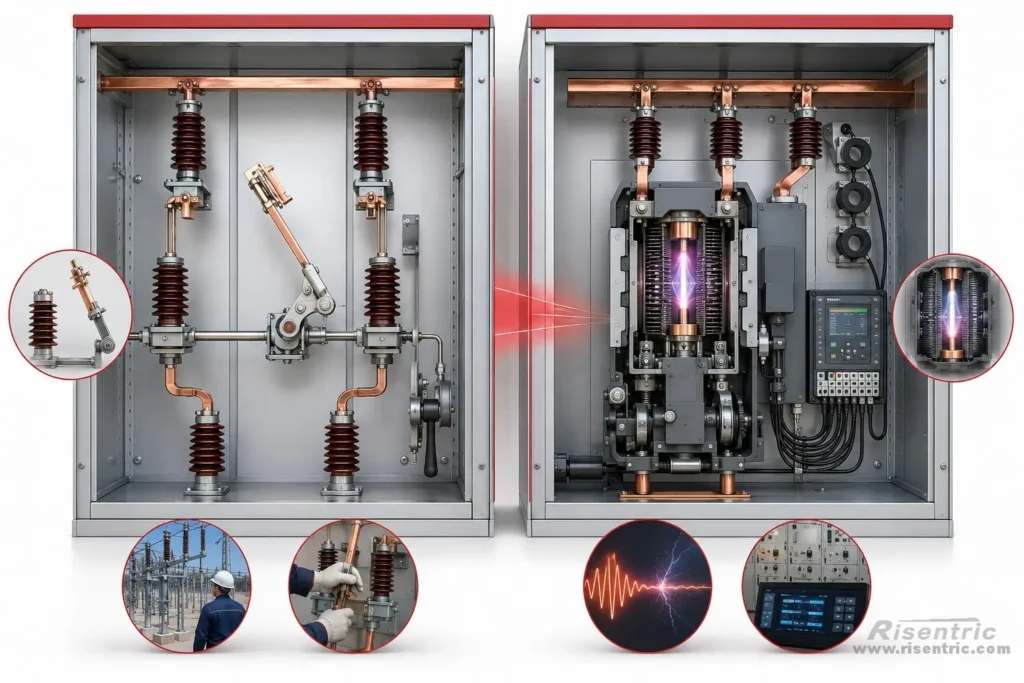
| Item | Isolator / Disconnector | Circuit Breaker |
|---|---|---|
| Main function | Physical isolation | Switching and protection |
| Current interruption | Normally off-load only | Can interrupt load and fault current |
| Arc extinguishing design | Usually no strong arc-extinguishing design | Yes: vacuum, SF6, air arc chute, etc. |
| Protection function | No | Yes, with relay or trip unit |
| Structure | Moving blade/contact + air gap | Contacts + arc chamber + trip mechanism |
| Operation condition | After breaker opens | Under load or fault condition |
| Cost of device itself | Simpler, usually cheaper than breaker | More complex, more expensive |
| Design impact | Can be large in MV | Main protection device |
| Typical use | Fixed MV switchgear, substations, isolation points | LV/MV protection and switching |
A normal isolator has no strong arc-interruption design and is intended for off-load operation. A switch-disconnector or load-break switch is different because it is designed to break rated load current.
Conclusion
In MV switchgear, isolator is a primary current-path device with contacts, insulation distance, operating mechanism, interlocks, and busbar connections.
It is useful in fixed MV switchgear because the breaker cannot be withdrawn. But in withdrawable MV switchgear or many LV panels, the isolation function is already provided by the draw-out structure, breaker, or switch-disconnector.
The main purpose of a separate isolator is to provide a safe maintenance isolation point, especially in fixed-type MV switchgear.
FAQ
Is an isolator the same as a circuit breaker?
No. A circuit breaker interrupts load current and fault current. An isolator mainly creates a physical isolation gap after the circuit has already been switched off.
Can an isolator break load current?
A normal isolator is usually an off-load device and should not be used to break load current. If the device is designed to break rated load current, it is usually called a switch-disconnector or load-break switch.
Why is an isolator used in fixed MV switchgear?
In fixed MV switchgear, the breaker cannot be withdrawn. A separate isolator provides a physical separation point from the live busbar, which is useful for maintenance.
Is an isolator needed in withdrawable VCB switchgear?
Usually not. In withdrawable VCB switchgear, the breaker truck can be racked out to the test or isolated position, so the draw-out structure already provides the isolation function.
Why is a separate isolator rare in low-voltage switchgear?
In low-voltage switchgear, isolation is often already provided by the ACB, MCCB, MCB, switch-disconnector, or fuse switch-disconnector. Adding another isolator may only duplicate the same function.
Does adding an isolator change the switchgear design?
In MV switchgear, yes. An isolator is part of the primary current path. Adding it may require extra space, copper links, support insulators, interlocks, operating mechanisms, and changes to the cabinet layout.


