
Note: This article is Part II of our Three-Phase Power series.
In Part I, we explained the basic difference between single-phase and three-phase power. In this article, we move from basic theory to real electrical equipment, with a focus on switchgear.
Three-phase power is not only a waveform concept. Once it enters real distribution equipment, it becomes a structural design problem: how should the panel receive, distribute, switch, protect, measure, and isolate three related live conductors?
This is why switchgear is one of the best places to understand three-phase power in practice.
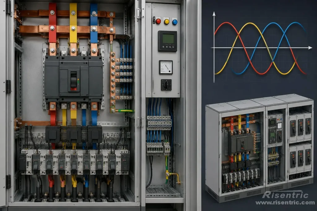
A transformer changes voltage. A voltage regulator stabilizes voltage. But switchgear shows the three-phase system most directly. Inside the cabinet, L1, L2, and L3 become phase busbars, breakers, terminals, CTs, meters, cables, and outgoing feeders. If the system includes neutral and protective earth, N and PE also become part of the physical structure.
So in switchgear, three-phase power is not only an electrical supply type. It directly affects the internal arrangement of the panel.
Quick Review: What Three-Phase Power Means

Three-phase power uses three AC voltage waveforms. These waveforms have the same frequency, but they are separated from each other by 120 electrical degrees.
In a balanced three-phase system, the three phases work together to deliver power more smoothly than a single-phase system. This is one reason three-phase power is widely used in industrial and commercial power distribution.
In drawings, labels, and technical documents, three-phase systems may appear in different forms:
| Marking | Common meaning |
|---|---|
| L1, L2, L3 | Three phase conductors in many electrical systems |
| R, S, T | Another common way to mark the three phases |
| A, B, C | Phase labels often used in drawings, specifications, and some regional standards |
| U, V, W | Common terminal markings for three-phase motors |
| 3P | Three phases, usually without neutral switching |
| 3P+N | Three phases plus neutral |
| 3P+N+PE | Three phases, neutral, and protective earth |
These markings are not only naming habits. They affect real switchgear design, including busbar arrangement, breaker pole number, neutral design, metering wiring, cable termination, protection, and quotation.
Line-to-Line and Line-to-Neutral Voltage in Switchgear

Before introducing the structure of busbars, it is better to start with one point: three-phase switchgear may distribute more than one voltage relationship.
A simple way to imagine this is three equal streams flowing together as one river. Each stream represents one phase: L1, L2, and L3. If a load uses only one phase and neutral, it is like taking water from one stream. If a load uses the phases together, it is like using the combined flow of the three-phase system.
In actual switchgear, these “streams” are not water. They are physical phase conductors or busbars. L1, L2, and L3 become three phase busbars. If the system includes neutral, N becomes a neutral busbar or neutral connection path.
This creates two common voltage relationships:
| Voltage relationship | Meaning | Example |
|---|---|---|
| Line-to-line voltage | Voltage between two phase conductors | L1-L2, L2-L3, L3-L1 |
| Line-to-neutral voltage | Voltage between one phase and neutral | L1-N, L2-N, L3-N |
For example, in a common 400/230 V system, 230 V is the voltage from one phase to neutral, while 400 V is the voltage between two phases.
The 400 V is not created by the switchgear. It comes from the three-phase voltage relationship. In a balanced star-connected system, the three phase voltages are separated by 120 electrical degrees, so the voltage between two phases is √3 times the phase-to-neutral voltage.
Line voltage = √3 × phase voltage
So:
400 V ≈ 230 V × √3
This is why the same switchgear panel may supply both types of loads:
| Load type | Typical voltage use |
|---|---|
| Three-phase motors, pumps, compressors | 400 V line-to-line |
| Lighting, sockets, control circuits | 230 V line-to-neutral |
This formula matters because it affects real switchgear design. If the panel only supplies three-phase loads, neutral may not be required. But if it also supplies single-phase loads, the panel may need a neutral busbar, neutral terminals, 4-pole breakers, earth leakage protection, and proper load distribution across L1, L2, and L3.
Therefore, “400 V three phase” is not enough information for switchgear design. The supplier still needs to know whether the system is 3P, 3P+N, or 3P+N+PE, and whether the outgoing loads are three-phase, single-phase, or mixed.

Looking for factory-tested 3-Phase switchgear & Panel boards for your project?
Why Three-Phase Power Changes Switchgear Design
Three-phase power changes switchgear design because the equipment must handle three live conductors that are electrically related to each other.
In a single-phase circuit, the panel mainly controls one live conductor and one return path.
In a three-phase circuit, the switchgear must receive, distribute, switch, protect, measure, and isolate L1, L2, and L3 at the same time.
This causes several important design differences.
1. Three Live Conductors Require a Three-Phase Busbar System

The first difference is physical.
A three-phase switchgear panel must distribute three live conductors: L1, L2, and L3. Each phase carries current, so each phase needs a clear and reliable path from the incoming side to the outgoing feeders.
This is why three-phase switchgear normally uses a three-phase busbar system.
| Busbar | Function |
|---|---|
| L1 busbar | Distributes phase L1 |
| L2 busbar | Distributes phase L2 |
| L3 busbar | Distributes phase L3 |
| Neutral busbar | Required when the panel supplies phase-to-neutral loads |
| PE busbar | Provides protective earthing connection |
If the panel only supplies three-phase loads, the neutral busbar may not be required. But if the panel also supplies lighting, sockets, control circuits, or other single-phase loads, neutral design becomes important.
This changes the cabinet structure. Compared with a simple single-phase panel, three-phase switchgear usually needs more internal space, stronger busbar supports, proper phase spacing, suitable insulation clearance, and more cable termination space.
In simple terms, the busbar system changes because three-phase power has more current-carrying paths. The switchgear must distribute these paths safely, separately, and consistently.
2. Three-Phase Loads Must Be Switched Together

Many three-phase loads are designed to operate with all three phases present at the same time.
Common examples include motors, pumps, fans, compressors, conveyors, industrial machines, and HVAC equipment.
For these loads, L1, L2, and L3 are not three independent circuits. They work together to create the required electrical and mechanical output.
If one phase is disconnected while the other two remain energized, the equipment may enter an abnormal operating condition. For motors, this is often called single-phasing. It can cause overheating, reduced torque, vibration, failed starting, or equipment damage.
This is why three-phase switchgear usually uses 3-pole or 4-pole switching devices.
| Device type | What it switches |
|---|---|
| 3-pole breaker | L1, L2, and L3 |
| 4-pole breaker | L1, L2, L3, and neutral |
The breaker design changes because three-phase loads should normally be connected or disconnected as one system. In most applications, the phases should not be controlled one by one.
3. Three-Phase Systems Have More Fault Paths

Three-phase systems also change switchgear protection because there are more possible fault paths.
In a single-phase circuit, common fault paths are usually live-to-neutral or live-to-earth.
In a three-phase system, faults may occur between phases, from phase to earth, or across all three phases.
| Fault type | Example |
|---|---|
| Phase-to-phase fault | L1-L2, L2-L3, L3-L1 |
| Phase-to-earth fault | L1-earth, L2-earth, L3-earth |
| Three-phase short circuit | L1-L2-L3 fault |
Because the fault possibilities are more complex, three-phase switchgear must be designed not only for normal load current, but also for fault current.
The design may need to consider breaker breaking capacity, short-circuit withstand rating, busbar bracing, protection relay selection, CT arrangement, earth fault protection, and coordination between upstream and downstream devices.
This is why three-phase switchgear is more than a normal distribution box. It must distribute power during normal operation and remain safe when abnormal fault conditions occur.
4. Three-Phase Fault Current Creates Mechanical Stress

During a short circuit, current creates heat. It also creates strong electromagnetic force.
In three-phase switchgear, the phase busbars are installed close to each other. When large fault currents flow through these busbars, strong forces can appear between the phases. These forces may try to bend, push, pull, or vibrate the busbars.
This is why three-phase switchgear must be designed not only for normal operating current, but also for fault conditions.
Important design factors include:
| Design factor | Why it matters |
|---|---|
| Short-time withstand current, Icw | Shows the current the assembly can withstand for a short duration |
| Peak withstand current, Ipk | Shows the peak mechanical stress the assembly can withstand |
| Busbar support strength | Helps keep busbars fixed during fault current |
| Insulator strength | Maintains safe separation between live parts |
| Joint quality | Reduces overheating and weak points |
| Mechanical bracing | Improves structural strength during short-circuit stress |
| Enclosure structure | Helps the whole assembly remain stable and safe |
This is one reason industrial switchgear is much more than a metal box with breakers inside.
The structure must survive both electrical heating and mechanical stress during abnormal conditions.
5. Phase Sequence Matters in Three-Phase Switchgear

Single-phase systems do not have phase sequence. Three-phase systems do.
Phase sequence means the order in which the three phases reach their voltage peaks. For example, the sequence may be:
L1 → L2 → L3
or:
L1 → L3 → L2
This order has real operational meaning because it affects the rotation direction of three-phase motors.
If the phase sequence is wrong, a motor may rotate in the opposite direction. For pumps, fans, compressors, conveyors, and production machines, wrong rotation can cause poor operation, process failure, or mechanical damage.
Because of this, three-phase switchgear must preserve and identify the phase order clearly.
Common design and commissioning considerations include:
| Item | Purpose |
|---|---|
| Clear phase marking | Helps installers and maintenance staff identify L1, L2, and L3 |
| Correct cable termination | Keeps the intended phase order from source to load |
| Phase sequence checking | Confirms the actual phase order during commissioning |
| Phase failure relay | Detects loss of one phase |
| Phase sequence relay | Detects wrong phase order |
| Commissioning inspection | Confirms correct operation before the system is put into service |
Phase sequence is therefore not only a wiring detail. It directly affects the operation of three-phase equipment.
6. Neutral Design Depends on the Three-Phase System Type
A three-phase system does not always need a neutral.
If the switchgear only supplies balanced three-phase loads, the system may use three phase conductors without a neutral conductor. Many motor feeders work this way.
However, many buildings and factories use both three-phase and single-phase loads. In that case, the neutral becomes important because single-phase loads often connect between one phase and neutral.
| Load type | Typical connection |
|---|---|
| Three-phase motor | L1-L2-L3 |
| Single-phase lighting | L1-N, L2-N, or L3-N |
| Single-phase socket circuit | L1-N, L2-N, or L3-N |
| Control circuit | Phase-to-neutral or phase-to-phase, depending on design |
If the switchgear supplies these phase-to-neutral loads, the panel may need a complete neutral arrangement.
This may include:
| Item | Purpose |
|---|---|
| Neutral busbar | Provides a common neutral connection point |
| Neutral terminals | Allows outgoing neutral connections |
| Neutral current consideration | Ensures the neutral path is suitable for actual load conditions |
| 3P+N arrangement | Defines the system as three phases plus neutral |
| 4-pole breakers | Allows the neutral to be switched when required |
| Earth leakage protection | Provides additional protection for certain outgoing circuits |
| Single-phase load distribution | Helps reduce serious imbalance across L1, L2, and L3 |
So neutral design changes because three-phase distribution systems often supply both three-phase loads and single-phase loads. The switchgear must be designed according to the actual load structure, not only the incoming voltage.
7. Three-Phase Metering Must Measure All Phases

In a single-phase panel, metering is relatively simple because there is usually only one main live conductor to measure.
In a three-phase switchgear panel, metering must normally measure all three phases. This is because L1, L2, and L3 may carry different currents, especially when the panel supplies both three-phase and single-phase loads.
A three-phase metering system may require:
| Metering item | Why it matters |
|---|---|
| Voltage input from L1, L2, and L3 | Allows the meter to measure the three-phase voltage condition |
| CTs on L1, L2, and L3 | Measures the current of each phase |
| Correct CT ratio | Ensures the displayed current and power values are accurate |
| Correct CT direction | Prevents wrong power direction or abnormal readings |
| Correct phase sequence | Helps the meter calculate three-phase power correctly |
| Neutral connection if required | Needed for some meters in 3P+N systems |
If CT wiring is wrong, the meter may show incorrect current, wrong power factor, wrong active power, or abnormal reverse power.
This is why three-phase metering is more sensitive to wiring correctness. A three-phase system cannot be accurately understood by measuring only one conductor.
8. Feeder Layout Must Consider Three-Phase and Single-Phase Loads
Switchgear does not only receive power. It also divides power into outgoing circuits.
In a three-phase switchgear panel, outgoing feeders may supply different types of loads:
| Feeder type | Typical application |
|---|---|
| Three-phase feeder | Motors, machines, pumps, compressors |
| Single-phase feeder | Lighting, sockets, small equipment |
| Motor feeder | Motor control circuits or motor loads |
| Distribution board feeder | Downstream DB, panelboard, or load center |
| UPS feeder | UPS input or output distribution |
| HVAC feeder | Chillers, fans, pumps, air-conditioning equipment |
| Lighting feeder | Lighting distribution circuits |
| Socket feeder | General power outlets or small equipment circuits |
If many single-phase loads are connected to only one phase, that phase may carry much more current than the others. This may cause phase imbalance, higher neutral current, uneven transformer loading, voltage instability, overheating risk, or unexpected tripping.
In three-phase switchgear, feeder layout is part of the electrical design. The designer should consider how outgoing single-phase and three-phase loads are distributed across L1, L2, and L3.
9. Cable Termination Becomes More Complex

Three-phase switchgear usually needs more conductors and more cable space than a simple single-phase panel.
A three-phase feeder may use different cable arrangements depending on current rating, neutral requirement, installation method, and project specification.
| Cable arrangement | Typical use |
|---|---|
| 3-core cable | Three-phase loads without neutral |
| 4-core cable | Three phases plus neutral, or three phases plus protective conductor depending on project practice |
| 5-core cable | Three phases, neutral, and PE |
| Single-core cables | Large-current feeders or flexible cable routing |
| Parallel cables per phase | High-current switchgear where one cable per phase is not enough |
This affects the physical design of the switchgear, including:
| Design item | Why it matters |
|---|---|
| Cable entry direction | Determines whether cables enter from top, bottom, front, or rear |
| Gland plate design | Supports correct cable fixing and sealing |
| Terminal size | Must match the cable cross-section and quantity |
| Bending radius | Requires enough internal space for safe cable routing |
| Phase identification | Helps prevent wrong phase connection |
| Heat dissipation | Important when many large cables are installed |
| Maintenance space | Allows inspection, tightening, and future cable work |
For high-current LV switchgear, cable termination space can become a major part of cabinet design.
This is another practical reason why three-phase switchgear must be designed according to the real project conditions, not only the rated voltage.
The Basic Formula Behind Three-Phase Equipment Sizing

Three-phase switchgear is selected mainly according to voltage, current, short-circuit level, and system structure.
Among these, current is especially important because it affects breaker rating, busbar rating, CT ratio, cable size, and heat dissipation.
For balanced three-phase apparent power, the basic formula is:
S = √3 × VL × IL
Where:
| Symbol | Meaning |
|---|---|
| S | Apparent power, in VA or kVA |
| VL | Line-to-line voltage |
| IL | Line current |
For example, if a three-phase load is 100 kVA at 400 V, the line current is:
IL = 100,000 ÷ (√3 × 400)
IL ≈ 144 A
This means a 100 kVA, 400 V three-phase load has a line current of about 144 A.
It should not be calculated as:
100,000 ÷ 400 = 250 A
That calculation ignores the three-phase relationship.
This formula matters because switchgear is not selected only by kVA. The supplier must convert project load information into practical current ratings for breakers, busbars, CTs, and cables.
The same logic also applies to transformers and voltage regulators. A 100 kVA three-phase transformer or 100 kVA three-phase regulator usually means total three-phase capacity, not 100 kVA per phase.
Looking for factory-tested 3-Phase switchgear & Panel boards for your project?
Simple Comparison: Single-Phase Panel vs Three-Phase Switchgear
| Area | Single-phase panel | Three-phase switchgear |
|---|---|---|
| Main conductors | L, N, PE | L1, L2, L3, optional N, PE |
| Voltage relationship | Usually one main voltage | Line-to-line voltage and possibly line-to-neutral voltage |
| Busbar system | Simpler | Three-phase busbars, possible neutral and PE busbars |
| Breakers | 1P, 1P+N, or 2P | 3P or 4P |
| Fault paths | Fewer | More phase-to-phase and phase-to-earth fault paths |
| Protection | Basic overcurrent and earth leakage | Overcurrent, short circuit, earth fault, phase loss, phase sequence, imbalance |
| Metering | One voltage/current path | Three voltage/current paths, usually CTs on all three phases |
| Phase sequence | Not relevant | Important for motor direction |
| Neutral design | Usually straightforward | Depends on 3-wire or 4-wire system |
| Cable termination | Simpler | More conductors, larger terminals, and more space |
| Quotation | Usually simpler | Requires SLD, feeder list, fault level, neutral requirement, and pole number |
Quick Summary
Three-phase power changes switchgear because the panel must handle L1, L2, and L3 as one coordinated electrical system.
This affects the busbar system, breaker pole number, protection design, metering, phase sequence, neutral arrangement, cable termination, and short-circuit withstand requirement.
The key point is simple: three-phase switchgear is not just a larger single-phase panel. It must distribute, switch, protect, measure, and isolate three related live conductors safely.
This article focused mainly on switchgear because switchgear shows the three-phase system most directly. Three-phase power also changes transformers and voltage regulators, but in different ways. We will discuss those topics in separate articles.
FAQ
Is three-phase switchgear just a larger single-phase panel?
No. Three-phase switchgear must handle L1, L2, and L3 together. This changes the busbar system, breaker pole number, protection design, metering, phase sequence, neutral design, and cable termination.
Why does 400/230 V appear in three-phase systems?
In a balanced star-connected system, line voltage is √3 times phase voltage. So a 400/230 V system has about 400 V between phases and about 230 V between phase and neutral.
Why do three-phase breakers usually have three poles?
Because three-phase loads normally need all three phases to be connected or disconnected together. A 3-pole breaker switches L1, L2, and L3 at the same time.
When does three-phase switchgear need a neutral?
A neutral is usually needed when the panel supplies single-phase loads, such as lighting, sockets, control circuits, or small equipment connected between phase and neutral.
Why does phase sequence matter?
Phase sequence affects the rotation direction of three-phase motors. Wrong phase sequence can make motors rotate in the wrong direction.
Why is short-circuit rating important in three-phase switchgear?
During a short circuit, high fault current creates heat and mechanical force. The switchgear must withstand these stresses until the protection device clears the fault.
Are three-phase transformers and voltage regulators also different?
Yes. Three-phase transformers and voltage regulators are also different from their single-phase versions. However, their differences come from other design principles, such as winding connection, voltage regulation method, neutral requirement, and capacity calculation. These topics are better discussed in separate articles.